Free Shipping
Aloha Deluxe Travel Trailer Plans
Build a Deluxe Vintage Camping Trailer with Shower

|
Aloha Deluxe Travel Trailer Plans
Build a Deluxe Vintage Camping Trailer with Shower
 |
PDF Format |
|
|
All Orders Processed
On a Secure Server
|
Price $12.95
|
|
Get a restored copy of these Aloha Deluxe Travel
Trailer Plans with 15 Pages of Enhanced and Enlarged Figures
and Illustrations and Searchable Text.
|
We will email these plans, to the address provided
with your payment, within 48 hours following receipt of your order.
|
|
|More
Vintage Trailer Plans|
|
|

|
|
|
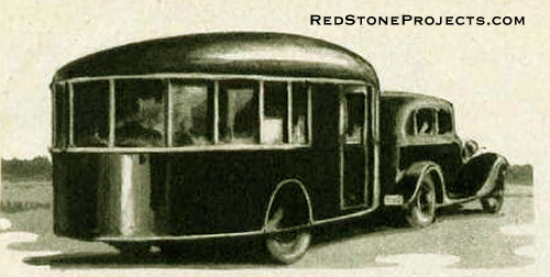
"Aloha" is a real traveling
home. Fitted with a shower, berths, and a kitchen, it has the best of conveniences
without the customary crowding and costs little to build.
|
| TRAILER season is here. Those who are making travel plans
are certain to welcome any suggestion that will fulfill their dreams in
an economical, safe, convenient and comfortable manner. It is believed
the Aloha, trailer deluxe, meets with these requirements. |
 |
|
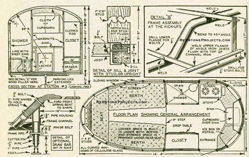
Figure 1. Floor plan shows shower, closet, stove,
sink, refrigerator, and baths of well-equipped Aloha. Unusual arrangement
provides many conveniences minus crowding. Wood frame is fastened to chassis
channel iron with one-fourth inch bolts.
|
|
| If a trip of any length at all is planned, every
convenience possible should be provided to get the most in pleasure and
comfort from the trailer. What could be more disappointing in your travels
than to find a delightful spot to stop for a while, only to realize you
are not equipped for unplanned stopovers.
A shower is always refreshing and regardless of where
you are there are times when you would like a little pepping up. This pleasure
may be enjoyed even while you are on the road. Many times, there are occasions
when something a little nicer than driving or camping togs would be more
presentable. The writer has designed this trailer to provide all these
conveniences and benefits and many more as will be disclosed later, at
a cost no greater than the average well designed trailer. Yet Aloha is
no more difficult to construct. |
|
Figure
2. Complete Chassis Metal Framing - Plan and Elevation Six cross bars are
welded to the two-inch chassis pipe frame. The frame bends over the axle
to aid balance of trailer. Lay out the rear curve of the body frame by
making full size squared frame. Radius of major front curve is 41 inches.
|
Get a restored copy of these Aloha Deluxe Travel
Trailer Plans with 15 Pages of Enhanced and Enlarged Figures
and Illustrations and Searchable Text.
All Orders Processed
On a Secure Server
|

|
| Aloha has the good features of a number of designs with
many new ones added, making the completed cabin one of unique arrangement
and beauty. You will be proud of this trailer anywhere.
Although this design is not a perfect streamlined job,
still every effort has been made to cut down its head resistance and the
vacuum at the rear. The roof has also been treated in a similar manner
to reduce air friction along its entire surface. All these changes have
been made without losing interior convenience, or comfort and with these
changes it is safe to say that the cost of towing this trailer will be
less than 4 percent more than the cost of running your car.
The chassis has a double bend over the axle to provide
a large stowage space at the stern. The road clearance is 12 inches at
all points except at the parking leg which has a minimum clearance of 8
inches. Another feature of this chassis is the added floor length. It has
been found that the average floor length in other trailers is 12 feet and
the overall dimension from rear to tip of drawbar is 15 feet. In this design
the floor length is 4 feet 6 inches and the overall length is 15 feet 9
3/4 inches. Due to the curved front of the chassis this trailer will allow
the towing car to turn in a radius as sharp as that allowed by any other
trailer design.
The chassis consists of two 2-inch pipes, having two vertical
bends over the axle and one horizontal bend near the bow. The bow ends
are brought together and welded to a short length of 1 3/4-inch pipe vertically
placed with one end 2 inches below the larger pipes. This vertical pipe
is called "parking leg housing," which will later be described. We next
weld to the chassis frame before it gets out of line. 1/4-inch x 1 1/4-inch
x 1 1/4-inch angle iron joists which are spaced and of the lengths indicated.
Care must be exercised to see that the joists are at right angles to the
center line of the two chassis frames which are separated as shown on the
drawings. Two pieces of 2-inch channel iron are then bent to the curves
indicated and welded to the ends of the joists with the upper channel flange
faces level with upper edges of the joist vertical flanges.
It will be noted that the two joists nearest the wheel
wells are considerably above the ends of the channels. These loose ends
may be tied together by welding a short piece of angle iron vertically
to the joist and channel ends. A spreader welded to the undersides of the
chassis at the after bends as shown on the drawings and which is another
piece of angle iron of the same size described above will act as the upper
support of the fuel tank. For added safety factor, in case of overloading
the stowage compartment, we next weld two pieces of 1/4 inch x 1 ¼
inch strap iron to the bottom of the stern channel bar near the center
line and to each pipe chassis member at the point where the after bend
is located, just aft of the wheel well.
The method of securing axle to springs as shown on the
drawings is an extremely simple one and is shown as a second alternative
only. To secure the axle assembly to the chassis, four ''U" shaped lugs
made of 1/4-inch steel will have to be welded to the pipe frame. The exact
location and spacing of these lugs will directly depend upon the type and
equipment used. Be sure, however, that the clearance between the top of
the axle housing and the bottom of the pipe frames is at least 4 inches
when assembled. |
|
|
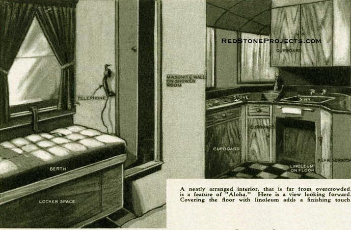
A neatly arranged interior, that is far from overcrowded,
is a feature of "Aloha" Here is
a view looking forward. Covering the floor with Linoleum adds a finishing
touch.
|
| The drawbar is next in line and two suggestions are offered.
The spring arrangement is the writer's first choice and consists of a Ford
front axle spring bent in the manner shown and bolted Inside a 2-inch pipe
that has been formed to receive it. As each car presents its own problem
for hooking on a trailer, the height on the chassis frame elevation is
not given and details of connections are omitted.
After this height has been determined by the builder,
the formed length of pipe is then welded to the two 2-inch pipe frames
and the top of the parking leg housing. Care must be taken not to get the
length of the spring shorter than is specified, or there will be future
trouble at sharp turns.
The parking leg consists of two pieces of pipe telescoping
within the housing. They are held in position while traveling by means
of a pin passing through the bottom ends of the housing and the two pipes.
In parking position, the pin passes through the housing and the larger
of the two pipes as will be readily seen in the detail. A flat metal foot
welded to the bottom of the smaller pipe will keep the leg from sinking
into the ground.
This completes the chassis and you are ready for framing
of sides and roof, but before proceeding a word of advice here may be useful.
The water tanks may or may not be used as they are indicated on the drawings,
or you may feel that only one will suffice. The writer has found in similar
matters that it is better to have too much than not enough when it is most
needed. This job is extremely stable because of its low center of gravity.
The possibility of capsizing is remote but if this design did not have
these features, the low-slung water tanks would establish them. Consider
then the added advantages here plus a large source of water supply. The
method of hanging these tanks is accomplished by welding two it straps
at the ends and undersides of the respective tanks. The free ends of the
straps are bent up and over the tops of the pipe frames end welded.
The placing of the tanks concludes all the welding there
is to be done and all the heavy iron work. Unless you have ready access
to welder's outfit and know what you are doing, it is strongly recommended
that this work be done by a man who thoroughly understands his business.
The body is built after the chassis is completed. Check
the chassis to be certain it is square and plumb. The wheel alignment must
be true and at right angles to the line of pull, which will be the chassis
centerline.
Then you are ready to proceed with building up the body.
Here a band saw would come in handy, but if you haven't one, you will be
in no worse position than the writer. It will be noted in the chassis drawing,
that the flanges of the channel iron face outward. This is in order that
a wood member 1 1/2 inches x 1 3/4 inches may fit snugly in the channel.
This sill may be placed in two ways, either by steaming and bending to
shape or cutting in the required curve. In either case, this wood sill
is bolted to the channel iron using 1/4- inch stove bolts placed at 2-inch
centers.
Next cut the required number of frame studs to hold the
side rail strips and plates 6 inches. At the dimensions shown on the plans
3/4-inch x 3/4-inch x 2-inch cleats are nailed on both faces of the studs
to hold the side rails strips and plates. Notch out one end of each stud
and the sill where the studs occur to form a snug mortise joint, and bolt
the studs to the sill with 1/4-inch stove bolts. Be sure that the outer
faces of the studs are flush with the outer face of the sill where the
studs occur to form a snug mortise joint, and bolt the studs to the sill
with 1/4-inch stove bolts. Be sure that the outer faces of the studs are
flush with the outer face of the sill. |
|
Figure
3. Cross Section Thru Frame at Door, Window, and Studding - Details of
windows and doors illustrate construction recommended. Floor is laid to
extreme edge od chassis sill frame except at door, as shown, and at wheel
wells. Note that window stool and screen frame are hinged to permit window
to be lowered. Auto door lock is best for door.
|
Get a restored copy of these Aloha Deluxe Travel
Trailer Plans with 16 Pages of Enhanced and Enlarged Figures
and Illustrations and Searchable Text.
All Orders Processed
On a Secure Server
|
| Nailing snips are now to be placed where the lower set
of deals occur. To get the correct curves for these members lay the raw
material on the sill between their respective studs and mark the outer
curve of the sill at the same time keeping the inner edges in a straight
line. Establish the respective angles at the ends for nailing to the studs
to form a neat joint This nailing strip need not be more than 3/4 inch
thick and occurs only where disappearing windows are not used. A study
of the details will explain existing conditions there.
The top side rail or plate members are cut and fitted
in a similar manner but inch stock is recommended here. Assuming that all
the plate and nailing members are cut, take a pot of waterproof glue and
use freely. Then nail the rails in place against the cleats using a fair
size finishing nail. Temporarily brace the work so that it does not get
out of square or plumb while the glue is drying.
The roof is the next step and we begin by cutting the
longitudinal truss member, the piece that runs from front to rear of the
roof. Reference to the drawings will disclose the method of plotting this
curve. Plotting should be done on a large sheet of wrapping paper to form
a full-size pattern. We then lay this pattern on a level floor. Strips
of plywood 3/8 inches thick and 6 inches wide and as long as the curves
will permit are then laid over the curves of the pattern end to end. Make
good butt joints where the ends meet. Cover the upper faces of these pieces
with a generous coat of waterproof glue and lay on a layer of veneer or
plywood. Repeat this procedure until three layers me in place.
Mark off the points where the ribs join the truss member
and with 1-inch brads nail the assembly together. After the glue has dried
thoroughly, transfer the curves from the pattern to the rough truss thus
formed and cut along the lines drawn. Short lengths of white oak cut to
shape and spliced together can also be used for this truss piece.
The ribs are cut from plywood 1/2 inch thick and 2 inches
deep, and are cut from the same curve pattern. It will be noted that the
fore and after ends of the truss terminate in curves of 9-inch radius.
Continue the 9-inch arc, 3 inches longer than is required for the truss.
The next job is the framing of the windows. The inside
edges of the sills are cut in a straight line while the outside edges take
the curve of the body. There is sufficient space between the sills to pass
1/4 inch glass freely. |
| Our next step is to lay in the flooring. First cut strips
of wood 1 inch square, as long as necessary, and bolt them to the angle
iron joists using 1/8-inch stove bolts for the purpose. Lay 1/2-inch plywood
on these joists and fit carefully around the studs. Line the inside of
the wheel wells with 24-gauge sheet metal and apply two coats of red lead. |
|
|
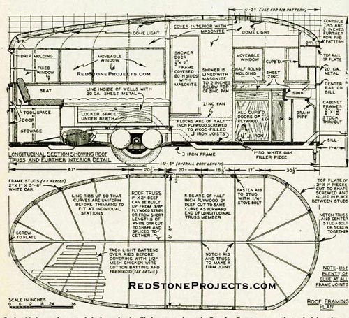
Figure 4. Studs, 23 in number, are bolted
to chassis sill frame as shown in Part 1. Front center stud, attached last,
is not fastened to sill, but to center rail because of trailer hitch. The
pattern for the lengthwise truss of the roof is also used for laying out
ribs. Tire pump develops air pressure in tanks under the body to force
water to shower and sink.
|
| To get an apparently seamless job for the sheet metal
sides of Aloha, the following instructions should be followed carefully.
The butted joints of all metal siding, which in this case is 20-gauge sheet,
metal are set in cement, the proportions and mixing of which is as follows:
to 8 pounds glazier's putty add I pound dry litharge and 1-pound dry red
lead. Mix this to a stiff consistency with boiled linseed oil. Do not overlap
the metal in tacking it down with the smallest nails possible. Spread cement
on the stud faces before tacking. Before the cement begins to set, scrape
off superfluous material until the seams are smooth. |
| The entire roof is covered with 1/2-inch mesh wire, shaped
to the curves of thin battens nailed to the ribs. Cover the wire mesh with
padding and then proceed to cut and fit the fabric top pieces which are
tacked temporarily in place. Chalk marks are then made where the seams
occur and the whole thing then pulled off and sewed together. Replacing
the finished fabric, it is pulled and stretched and tacked permanently
after which the drip molding is tacked in place.
The door is built up of two pieces of plywood 1/2 inch
thick and nailed and glued together. Cut an opening 12 inches x15 inches
and frame as shown the 1/2-inch detail. Cover the interior side with 1/4-inch
Presdwood or Mansonite and the exterior with 20-gauge metal, Cellulose
glass is used where curved windows occur.
Work on the interior treatment may now be started. At
this point all rough plumbing and electrical work should be installed.
Automobile dome lights should be affixed to the ceiling as desired.
The job now is to install the shower and closet and wardrobe
compartments. The shower pan is of zinc, 15 inches high with all joints
well soldered. The interior walls of the shower are lined with Masonite
which laps the pan edges at least 2 inches. The shower valve and head may
now be installed and finished up. The shower door consists of a 1/2-inch
x 2-inch frame covered on both sides with Masonite and hinged to swing
in. The closet and wardrobe are formed of Masonite on the exterior of frames
only.
The cabinet work is next and since it already has a floor
we build up the frames using 3/4-inch x 1 3/4-inch stock. All cupboard
doors are of 1/4-inch plywood. The counter shelf top of 1/4-inch plywood
covered with zinc. The sink is formed of this same material using care
to see that all joints are well soldered and particularly the drain connection
which leads to spill on the ground.
The refrigerator is insulated with two layers of 1/2 inch
Celotex on the sides and four layers on the bottom. Cover sides and bottom
with 26-gauge galvanized sheet metal. Provide the ice pan with a drain.
It will be noted on the Longitudinal Section that there
is an oil or gas tank located back of the water tanks. This is a standard
automobile gas tank. Pipes for filling the tanks should run to the exterior
of the cabin walls. Cover the ends with radiator caps. The type fuel used
for the stove will depend on the builders' choice. |
Any 2 Vintage Trailer Plans
$19.95 FREE Shipping |
|
Select 2 Vintage Travel Trailer Plans
|
|
|