Free Shipping on All U.S. Orders
All Orders Processed on a Secure Server
Build Your Own 3-4 Berth Caravan
Plans for a DIY Lightweight Vintage Camping Trailer
Building Your Own 3-4 Berth Caravan
by H.C. Piggin
|
| AFTER an initial "bedding-down" run of about 150 miles,
this van accomplished well over 1,200 miles of touring during August, 1958.
This included negotiating the usual bumpy sites, longish runs over granite
setts and very much second-class roads. Nothing was shirked in an effort
to find weaknesses, but apart front a little easily cured trouble due to
under springing, and a puncture, the longer journeys were quite uneventful.
The van towed well, and most of the time was hardly noticeable behind the
car, an early Vauxhall Wyvern.
In general, the construction is orthodox, although the
wooden main bearers are no longer in commercial fashion in these days of
cheap rolled channel-steel; however, they were chosen here to save weight
and to facilitate home construction. |
|
| Although throughout the accent is on ease of construction,
careless and shoddy work is inadmissible; a faulty joint or loose screw
may well spell danger and disaster to the driver and other road users.
A high degree of skillful craftsmanship is not necessary, ordinary careful
work being quite enough, but the home builder who is doubtful of his work
on any point will do well to consult tradesman, particularly over the road-worthiness
of the undercart.
So far as the woodwork is concerned only two joints -
the halving joint and the plain mortise-and-tenon joint are needed. An
hour or so spent in practicing these in scrap timber will be well worth
while. (See Fig. 8.)
Most of the metalwork consists of cutting angle-iron,
drilling it, and bolting it together ready for welding. Such welding as
there is should be carried out by a competent engineer.
Proprietary parts have been kept to a minimum so far as
possible in order to keep costs down. Apart from small fittings of a general
ironmongery order, only the corner jacks and the all-important ball towing-hitch
must be purchased. If expense is no object, then such items as proprietary
window frames, sink-unit and Calor-gas fitting will save time and improve
the van quite a lot. However, some modification of the plans shown here
will be necessary to accommodate the stock sizes of such fitments, they
should thus be carefully thought about before building begins. Indeed,
an intensive study of caravan periodicals and accessories catalogues is
an essential preliminary to any caravanning venture.
There is some prejudice against "non-proprietary", or
"home-built" vans, as so many of these are badly designed and worse constructed.
Many site-operators forbid such vans entirely, whilst others insist on
a
superficial inspection. It is as well, therefore, to ensure that only the
best is good enough, so far at outward appearance is concerned. |
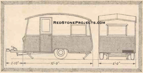
|
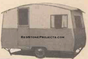
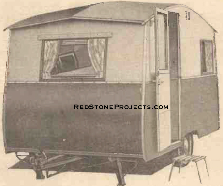
Figure 1. Side and rear views of the completed
caravan.
|
|
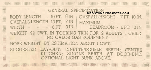
|
Caravan General Specifications
|
|
| The Axle and Wheels
Only sound work will suffice in the chassis. A poorly
made chassis will, apart from being a possible danger on the road, be a
constant source of trouble in towing, leading to all sorts of misbehavior
on the part of the van, which makes driving sheer hard work all the time.
Some home constructors may prefer to save time by purchasing
a ready-built chassis, but this will run to considerable expense.
The wheels of the caravan described here were adapted
from an old car front axle as follows.
First, all extra metal in the form of track-rod, shock
absorbers, etc. is removed. The wheels are then lined up with a very slight
toe-in, and the king-pins are welded-up solid.
The axle is then cut in the middle and extended to give
a track between tire centers of 5ft. 6in., by boxing across the center
with two pieces of angle-iron welded together and to the axle ends. (Fig.
2a.)
For steady, stable towing a wide wheel-base is necessary,
with as great a distance as possible between the springs to avoid "top
roll". (Fig. 2b.) |
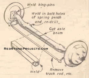
|
Figure 2a. Principal work on the axle.
|
|
| The Springs
These are removed and stripped. They should be cleaned,
reset and rebuilt with an extra leaf or two to a total of 9 in. X 3/16
in. The longer the springs the better.
As they are usually set at an angle on car front wheels,
the old bolt holes on the perches should be welded-in, and new holes drilled
so as to line up the springs at right-angles to the axle. The minimum distance
between the springs should be 3 ft. 2 in. If the spring perches can be
shifted wider apart it is certainly desirable to do so, but this may not
be possible on cranked axles.
On straight axles, the springs can be reattached below
the axle (underslung), so that a few inches of height reduction are obtained.
A low center-of-gravity is useful for stable towing.
It will be as well to strip and regrease the wheel-bearings
and to attend to the brakes (which should be of the cable-operated kind)
to see that the linings are good and the action free in operation.
Tires need not be new, but should certainly not be smooth.
In spite of rumors to the contrary, caravans do get punctures and bursts,
and as no "spare" is carried as a rule, such mishaps can be embarrassing
and involve considerable delay!
The axle and brake drums can be smartened up with a coat
of bitumen paint, and the springs can be sprayed with penetrating oil. |
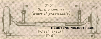
|
Figure 2b. The caravan Undergear.
|
|
| Main Chassis Bearers
Those consist of two soft. 10 ft. 6 in. lengths of 3 1/2
in. X 2 in. straight-grained prime ash. They must be free of all knots
and blemishes, and it is worth paying a little extra to get the best timber.
The size given is quite the minimum, and due allowance for planing must
be added.
After shaping, the bearers are bolted on to the springs,
using 3/8 in. diameter coach bolts with extra nuts as lockouts. (Fig. 3.)
It is important to mount the rear scroll with its shackle high, remembering
that it will settle under load. The bearers should be parallel to each
other, and should be braced apart until the flooring is secured. They should
also be levelled and supported on blocks until this is done. |
Get a restored copy of these vintage Build Your Own
3-4 Berth Caravan with 23 Pages of Enhanced and Enlarged Figures
and Illustrations and Searchable Text.
All Orders Processed
On a Secure Server
|
Figures
3, 4 and 5. Details of the main bearers, the floor assemble and tow. |
|
The Floor
In this design the floor is an integral part of the chassis.
It consists of 3/4 in. thick tongued-and-grooved deal boards, screwed on
to the ash bearers with 1 1/2 in. No. 9 steel screws. The boards must be
pulled
up tight together, and the screws inserted diagonally staggered, not in
straight rows. (Fig. 4.).
When all the flooring has been fitted according to plan,
the ends of the floorboards should by levelled and the 1 1/2in. X 1 in.
outrigger supports glued and screwed up tight under the ends of the boards.
At this stage, the complete floor and axle can be fairly
easily man-handled by four or five men. It should be turned over for ease
of fitting the ironwork - tow and corner jacks (Fig. 5). At this point,
too, the opportunity should be taken to apply several coats of bitumen
point to the underneath parts.
With the floor right way up, it can be levelled on its
jacks to await the mounting of the bodywork frames.
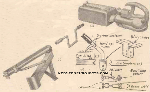
|
Figure 6. (a) "Ball" type of towing hitch; (b)
Hand brake; (c) Brace operated van leg.
|
|
| The tow-hitch is bolted on to the towing bar with high-tensile
bolts. These should be pulled up a little at a time, checking the over-ride
action occasionally to see that it remains free. If one bolt is overtightened
it is possible to warp the casing of the hitch and so cause the action
to bind (See Fig. 6a). The position of the brake-lever is fairly critical,
and should be checked carefully (Fig 6b). The brakes are connected-up and
adjusted so that they come on smoothly as the over-ride is forced back.
Final adjustment is best left until the van is ready for the road. The
brakes should never lock the wheels completely on the over-ride but, of
course, they must be fully applied on hand-pull.
Body Frames
All body frames are built from prime ash. The joints consist
mainly of straightforward mortise and tenons at "T"-junctions, and cross-halvings
at "through" points. All are glued with a waterproof resin glue, and secured
additionally with a 3/4 in. long No. 8 countersunk steel screw.
The end bends are made by soaking suitable lengths of
timber in a water-butt for at least 48 hours. Each is then cramped on to
a 1 in. thick oak board shaped to the required curve, and is left to dry
(fig 7.). Up to a week may be required to achieve the desired curve. It
is important that all ten bends must match up, and as they are made, they
should be lashed together and stored carefully on end until required.
Except for the spacing of the upright to allow for the
door, both side frames are identical.
It is as well to cut all timber to length and number each
piece as indicated in Fig. 9a. Then all parts which are to be of the same
dimensions can be placed together and marked-out in one operation, thus
ensuring identical accuracy for all floor and middle lengths, uprights,
corner bends, etc.
Note that the corner bends are fitted into mortises cut
at the necessary angle in the floor-lengths; the surplus is removed after
fixing, which is easier than trying to cut true "bridle" joints as such.
Assemble all joints temporarily to check their fit and
the truth of the whole framing. Then check the side frames together to
see that they are identical and quite flat.
The end flames shown in Fig. 9b present little difficulty.
Again, every care most he taken to ensure that they are identical with
each other. |
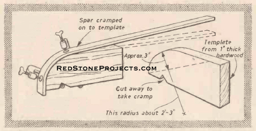
|
Figure 7. Method of making the end bends.
|
|
| Assembly of Frames on to Floor
The completed side frames are coach bolted into position
on the floor edge; the bolts, of course, pass right through the end supports
under the floorboards. The frames will require strutting temporarily to
prevent them from waving about.
The end frames are similarly bolted down.
The tops of the side-frames have to be nipped in" two
inches on to the headboards of the ends This places the side under slight
tension, and helps to give rigidity and stability.
The middle spars of the end frames are attached to the
corner bends with small, right-angle brackets, as can be seen in Fig. 9b.
This saves cutting an awkward joint which might weaken the bend. |
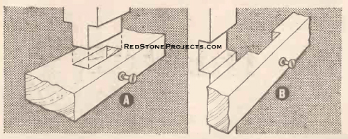
|
Figure 8. (a) A simple through mortise-and-tenon
and (b) cross-halving.
|
|
| The Roof Framing
The three roof bends can have their curves shaped whilst
the sides are being made, by wetting them and bracing them over a pile
of bricks. It is not essential to do this as the roof curve is quite a
small one, but it does help to reduce the tension.
The rafters are spliced to exactly the same angle as that
of the end frame heads (Figs. 9b and 10). Then the ends of the rafters
are halved and screwed on to the side frame roof bends. The rafters should
be braced temporarily at their centers until roofing is completed.
The roof bends are set down into their sockets, being
held with cramps until the screws are put in. It is as well to offer everything
on screws only at first, leaving the final gluing until all adjustments
have been made. |
Get a restored copy of these vintage Build Your Own
3-4 Berth Caravan with 23 Pages of Enhanced and Enlarged Figures
and Illustrations and Searchable Text.
All Orders Processed
On a Secure Server
|
Figure
9a. Details of the side framing.
|
|
Finally, the ends of all rafters are faired off the sides.
The ends of the roof bends are cut level, and are joined across with finishing
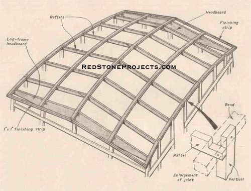
strips of 1 in. X 1 in. soft wood, glued and nailed into place (Fig. 11).
The rafters and the center roof bend, together with all
other protrusions on the roof, must all be faired-off to the main run of
the curve and slopes so as to get the maximum surface for setting down
the roof surface.
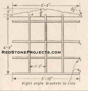
|
Figure 9b. The end frame.
|
|
| Wheel Boxes
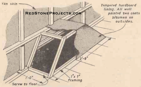
It is useful to build these in before the van is skinned.
The construction is quite simple and shown in detail in Fig. 12. |

|
Figure 10. Splicing rafters to suit slope of end
frame headboards.
|
|
| Skinning the Caravan
At this stage the Pram appears unduly fragile and not
very rigid, but the application of the skin will soon correct this.
On the van shown, the skin is 1/8 in. thick tempered hardboard,
which is entirely weatherproof in itself and has a long life.
Hints About Hardboard
A few general points about the fixing of hardboard will
be found useful. Each board should be well soaked with water for at least
48 hours; the backs should be sprayed quite wet, and the boards stored
back-to-back. This treatment, together with adequate fixing battens (the
recommended distance is 1 ft. 3 in., but the 1 ft. 6 in. of the framing
seems adequate), will help to prevent distortion. The best nails to use
are the special hardboard nails with square shanks and "lost heads" made
in coppered steel. They should be used at 3 in. to 4 in. intervals, and
fixing should begin at the middle of each panel, working outwards to the
edges and corners, making sure that all kinks are removed and that the
work lies flat. Panels should not butt up tight against each other; a gap
of 1/8 in. is permissible.
On the caravan, all hardboard edges should be bedded on
to a good layer of mastic sealer, and all points filled with this substance
well pressed home.
Before painting, the hardboard should be primed with special
hardboard sealer paint. All nails should be driven flush or a little below
the surface. All holes and blemishes should be stopped up after priming
(putty will do) and rubbed down well.
Bearing in mind these general points, the skinning of
the caravan will present few problems. The van shown was skinned with large
surfaces for quickness, cut from 12 ft. X 4 ft. sheets. Apart from some
waste involved at the curves, this method has shown no drawbacks, although
the use of smaller sheets may be more economical. However, the large joint-free
surfaces are certainly neat and watertight.
The Sides
The bottom side panels were put on first, having been
offered to the framework for careful marking out. The top sides followed
the windows being cut out beforehand. Then the ends were dealt with, being
allowed to overlap the sides as the corners. |
|
Figure 11. General view of roof framing.
|
|
| The Roof
The roof was put on in two pieces, these being offered
to the job, marked off and cut. The first piece is fairly easy, being adjusted
to the middle of the center roof bend first and trimmed off at the edges
after fixing. The second piece has to be adjusted to give a neat joint
against the first at the center. This is best done by trial and error;
the hardboard is easily cut and planned. Again, it is better to allow the
roof to overhang at the eaves and to make this tidy after fixing. All sharp
corners should be glass papered off, and all nails made flush before applying
the roof canvas.
This is plain canvas and need not be of exceptional quality.
It should be 4 yds. long and 6 ft. 6 in. wide. From one end strips 4 in.
wide are cut, which are used first to seal the central joint, and any others
if the roof has been put on in smaller sections.
The canvas can be fixed either with an adhesive, or bedded
down on to wet paint. A liberal coat of either is applied along the joints,
and the canvas strips are pressed firmly into place. When the sealing strips
are dry, the main canvas is rolled and placed conveniently at one end of
the roof. An area about 1ft., or so, wide at a time is painted with adhesive
and the canvas is unrolled on to is, being pressed down and smoothed to
remove wrinkles, before proceeding with the next area. The canvas should
not be stretched tight. as it may split as it dries.
Any surplus canvas is trimmed off so as to leave an overhang
of about 1 1/2 in. This is turned under and pressed on to fresh adhesive
at the eaves, being fixed with copper tacks at 3 in. to 4 in. intervals.
At the ends the canvas is taken right under the overhang, and is glued
and tacked into the finishing strips.
When dry, the canvas is given a priming coat of lead-based
paint as soon as possible. This may be followed with as several coats at
the time of painting the whole van. |
|
Figure 12. Simple construction of the wheel box.
|
|
| The Windows
All surplus spars across door and window spaces should
be cut away, and the inner edge of the spaces rendered smooth.
The spaces for the door and opening-windows should be
primed and any holes stopped. They may then be undercoated to help seal
the hardboard. One excellent finish for these edges is to glue strips of
Formica along them. |
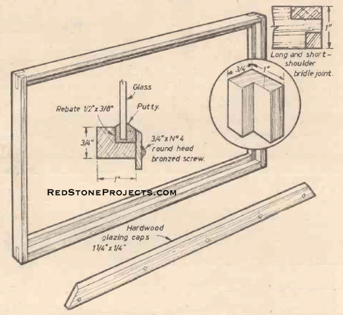
Figure 13. Construction details of the windows.
(Fixed windows may be a little lighter in section.) |
|
| After finishing the spaces, they should be most carefully
measured and the making of the doors and windows put in hand.
The windows are simple enough, being plain, rebated soft-wood,
with dowelled bridle-joints at the corners, as shown in Fig. 13. The hardwood
glazing strips are fixed with raised-head bronzed screws, using mitered
corners as shown. It is well to make up the whole window before glazing.
This is done with 24 oz. glass on ordinary linseed putty, and it is necessary
to prime all parts where the putty is going.
The fixed-window frames are nailed into place before glazing,
and the opening-windows are best hung without the glass. If the frames
have not been made too tight little difficulty will be had with fitting
these.
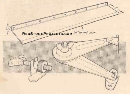
Each of the opening windows requires two friction stay
sets and at least one screw-up type of window-fastener of the type shown
in fig. 14 |
|
Figure 14. Window fittings. Shown here are a storm
pelmet for opening -windows made from 20 s.w.g. aluminum, a window fastener
and a friction stay -set.
|
|
| The Door
The bottom door is a plain panel of hardboard on softwood
framing. The upper door is glazed and is made from rebated softwood with
dowelled mortise and tenon joints. Both are hung on ordinary steel flap
back hinges which are allowed to protrude about 1/2 in. so as to swing
the doors clear of the van. The middle joint between the doors is made
up by false rebates nailed on (Fig. 15). |
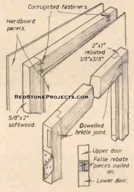
|
Figure 15. Details of the paneled lower door and
the glazed upper door.
|
|
| Exterior Fittings
The "J"-type roof guttering is screwed on to the roof
canvas overhang, being set on to half-dry paint.
The aluminum storm-strips over the opening windows are
similarly fixed, together with those at the doors. |
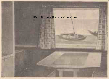
|
Figure 16. A photograph of the interior of the
author's caravan.
|
|
| Ventilators are fitted to the outside, one over the sink
and cooker unit, and one in the wardrobe. The positioning of these will
depend on the interior layout, of course, and must be plotted carefully.
It is as well to drill small holes through the hardboard at the corners
of the vents so as to plot the position of any extra fixing battens of
1 in. X 1 in. softwood which will have to be glued on to the interior of
the skin. The surplus skin between the fixings is cut away with a pad saw. |
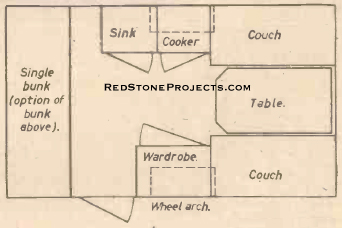
|
Figure 17. Suggested typical layout for 3-4 berths.
Couches and table make double bed. There is space for storage under couches
and bunk.
|
|
| The van should be primed and undercoated. However, it
is best to leave the final gloss until the van has been given a short tow
to shake things down.
all bright aluminum waist and corner moldings are screwed
on to wet undercoating any surplus being carefully rubbed off. Naturally,
the more care that is taken over the painting, the more professional will
be the final result. Plenty of patience, thin coats and good rubbing-down
in between will give the best results. |
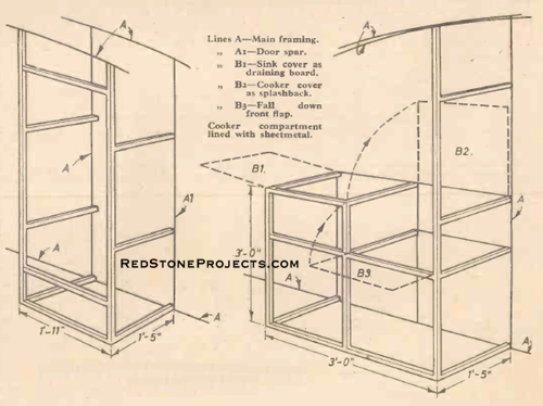
|
Figure 18. Framing details of the wardrobe and
sink/cooker unit.
|
|
| A number-plate, it should be pointed out here, is legal
necessity. Rear lights and reflectors are needed only if the van is towed
at night. And whilst on the subject of the law, it is as well to check
on the car insurance policy to make sure that the "third party" is valid
when a caravan is attached to the car. Wing mirrors on the car are also
necessary if a clear view through the front and rear van windows is not
obtained from the driving seat. |
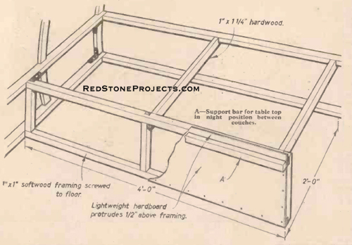
Figure 19. A dinette couch. Other couch and bunk
are of similar construction. Joints are halved, glued and screwed and the
1/8 in. hardboard top rests on
main van spar and front framing.
|
|
| The Interior
No one interior layout is entirely satisfactory to every
enthusiast, and as this part of the van is so dependent on personal choice,
only general guidance is given (Pics. 16 to 20).
In this small van with its light construction, the wardrobe
is essentially part of them main structure and helps to brace the roof
as also does one side of the cooker unit. It is desirable that both of
these should be kept fairly central, within six inches or so one way or
the other. The dimensions otherwise are not critical.
All furniture is permanently fixed and is built on to
existing mainframes wherever possible to save weight. Softwood framing
1 in. x 3/4 in will be found to be adequate for most pieces, being paneled
with lightweight hardboard (nominally 1/16 in. thick or 3 mm. ply). |
|
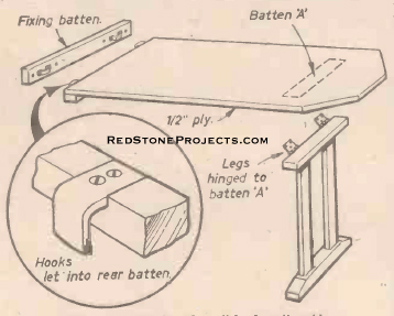
Figure 20. Details of a ""hook-on" table.
|
|
| Where weight is carried, as on seats and beds, the longest
unsupported run of framing is only 24 in., and some reinforcement of cross
members is necessary.
Doors are framed-up in the simplest possible style, use
being made of corrugated box-fasteners rather than complicated joints.
Walls are lined with 3 mm. ply; one of the pinky colors
such as Japanese lauan, or gaboon looks well and is relatively inexpensive.
It may be left plain or lightly toned with polish. It should be fixed with
small brass pins. |
|
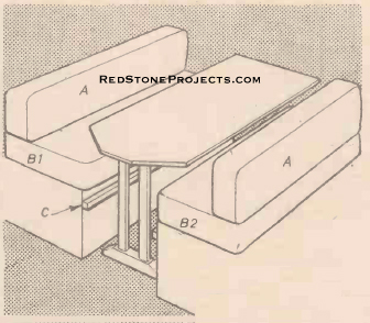
Figure 21. Dinette arrangement. By night table
rests on battens C. B1 lays on table and mattresses. Mattresses A are 12
in. wide. Mattresses B are 23 in. wide.
|
|
| Where fixings cannot be obtained on existing framing,
small 1 in. cubes of softwood can be glued on to the caravan skin at about
6 in. intervals. When cutting the plywood, the use of templates cut from
stout paper is recommended for the awkward shapes.
In small vans it is advisable to keep the interior light
in finish. The roof should be painted dead white, and all interior woodwork
and hardboard should be lacquered in pale tones - birch grey is very pleasant
- perhaps relieved occasionally by some brighter contrast here and there.
Useful ideas can often he obtained by inspecting commercially-built caravans. |
Any 2 Vintage Trailer Plans
$19.95 FREE Shipping |
|
Select 2 Vintage Travel Trailer Plans
|
|
|

