Free Shipping on All U.S. Orders
All Orders Processed on a Secure Server
Mini Steam Engine Made with Simple Hand Tools
Plans for an actual working model that
requires no lathe, castings, or nuts and bolts.

|
Working Model
Mini Steam
Engine Plans
Built with Basic Hand Tools
 |
PDF Format |
|
|
All Orders Processed
On a Secure Server
|
Price $12.95
|
|
Get a restored copy of these vintage Steam Engine
Plans with 5 Pages of Enhanced and Enlarged Figures and Illustrations
and Searchable Text.
|
We will email these plans, to the address provided
with your payment, within 48 hours following receipt of your order.
|
|
|More Vintage Project
Plans|
|
|
  
|
  
|
Mini Steam Engine Made with Simple Hand Tools
Actual working model requires no lathe,
castings, or nuts and bolts.
By Andy Sprague and Fred Wolff
|

|
|
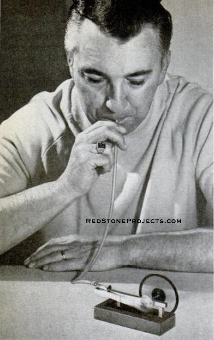
Mini Steam Engine operates through air blown through
tube, either by mouth or connection to low pressure air supply, or by connection
to "teakettle" boiler on stovetop.
|
| IF YOU HAVE BEEN WAITING for a model engine that doesn't
require a shop full of tools to make it, here's one which is about as simple
to build as you could hope for. You can make it with hardly more than a
soldering iron, hand drill, file and hacksaw. And it really runs!
It's made entirely of common hobby shop materials, 1/4-in.
square brass tubing for the most part, a washer, a brass nail and a spring
from a motor brush. The flywheel is a clock gear with its teeth filed off
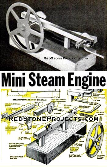
(See Mini Steam Engine Parts and Assembly Details Figure for a complete
list of parts and dimensions). |

|
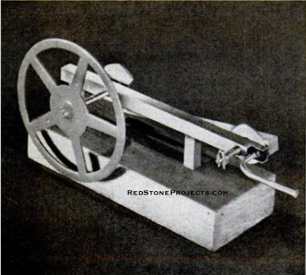
Crankshaft tube is soldered to horizontal member,
leaving 1/16 in. protrusion
for mounting the crank.
|
| Begin by cutting a 4 1/2-in. length of 1/4-in. square
tubing for the horizontal member to which all other parts are connected.
Then drill the 1/8-in. hole through the tubing on the center line for the
crankshaft tube. Drill the 1/16-in. hole 7/16 in. from the opposite end
and parallel to the crankshaft hole. Finally, drill a 3/16-in. hole through
one side of the tube only. Use the previously drilled hole as a guide. |
Get a restored copy of these vintage Steam Engine
Plans with 5 Pages of Enhanced and Enlarged Figures and Illustrations
and Searchable Text.
All Orders Processed
On a Secure Server
|
Mini
Steam Engine Parts and Assembly Details
|
| The cylinder is of 1/4-in. square tubing 1 3/4 in. long.
Solder a 5/8-in. brass washer flat to the cylinder so that the washer's
center line is 7/16 in. from the end of the cylinder. Using a 1 1/4-in.
brass nail, solder its head exactly in the center of the washer hole.
To make the cylinder head, saw off a 1/4-in. square from
the 1/4-in. stock and tin one side. Then place it against the cylinder
head and sweat-solder it in position. Saw off the nail point and file two
vee grooves on both sides of the nail about 1/8 in. from the end and vertical
to the cylinder. These are for the wire clip that will hold the cylinder
tension spring in place.
Cut a 1/4-in. section of 1/8-in. tubing and solder it
to the center hole of the clock gear flywheel. Insert the crankshaft through
the tube in the horizontal member and solder the flywheel to the crankshaft.
The flywheel should spin easily. |

|
|
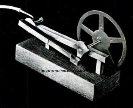
Piston and piston rod are one piece, made by sawing
a 3-in section of the 7/32-in. square tube.
|
| Next, calculate placement of steam/air ports by placing
the horizontal member with crankshaft side up, and rotate flywheel so as
to place the crank pin at a 90° angle to the horizontal member. With
a straight edge, then line up the crank pin with the cylinder hole and
mark the point at which it will line up with the center of the outer ring
of the cylinder washer when assembled. Reverse this procedure to determine
the location of the second port, then drill the 1/16-in. holes.
With the piston and cylinder in place you will need a
1/8 x 1-in. light coil spring to hold the unit together. The one used is
an electric-motor brush spring that can be obtained at an appliance repair
shop. Secure the spring in place with a small brass washer and U-clip made
from brass wire or rod.
To calculate the position of the cylinder port, revolve
the flywheel crank to a position 90' to the horizontal member. Looking
through one of the two holes, mark the point at which it hits the cylinder
washer. Disassemble the engine and drill a hole through the washer and
cylinder at the point marked. Reassemble; when the flywheel is revolved,
the cylinder port should hit both intake and exhaust ports respectively.
Again, disassemble and, using a section of 3/16-in. tubing,
solder the steam pipe to one of the two holes, depending which way you
want the engine to revolve. If excess solder has filled the holes, redrill
the intake pipe and exhaust port. |
Any 2 Vintage Plans
$19.95 FREE Shipping |
|
Select 2 Vintage Plans
|
|
|

