Free Shipping
Cruisemite Deluxe Travel Trailer Plans
Build a Vintage Steel Frame Camping Trailer
|
Deluxe Travel Trailer Plans
Build a Vintage Steel Frame Camping Trailer
 |
PDF Format |
|
|
All Orders Processed
On a Secure Server
|
Price $12.95
|
|
Get a restored copy of these vintage Cruisemite Deluxe
Travel Trailer Plans with 16 Pages of Enhanced and Enlarged Figures
and Illustrations and Searchable Text.
|
We will email these plans, to the address provided
with your payment, within 48 hours following receipt of your order.
|
|
|More
Vintage Trailer Plans|
|
|

|
|
|
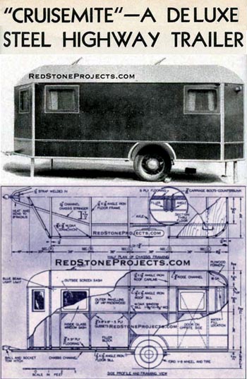
"CRUISEMITE" - A DELUXE STEEL HIGHWAY TRAILER
Designed for the person whose income is limited, this
camping coach is unique. It is of all-steel construction, yet cost no more
than inferior types.
|
 |
|
|
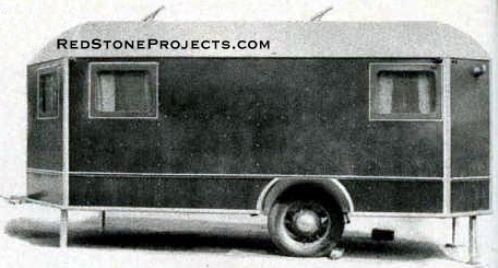
Completed Cruisemite, featuring conveniences found
only in expensive travel trailers.
|
| THE trailer Industry, having grown by leaps and bounds
during the past few years, it is difficult to determine just which type
to build. While there are streamline trailers, folding trailers, long trailers,
semi-trailers and any number of in between types, "Cruisemite" is a practical
coach for home construction. It has been seasoned by thorough testing and
free from undesirable features.
"Cruisemite" may be built in several ways with any number
of interior plans. That's half the fun of building a trailer: Planning
the interior yourself. A good standard layout is shown in the plans.
The secret of the easy-to-build part of "Cruisemite" is
that she has a steel chassis roof frame. This is welded up out of standard
steel channels and angles obtainable at any building supply dealer. A blacksmith
can be called upon to bend up the materials and weld the frames.
Being of steel, "Cruisemite" construction Is very strong,
as well as being very light. |
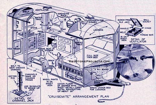
Cruisemite Arrangement Plan
On the original Cruisemite, this form of trailer hitch
was used. Being of the ball and socket type, the trailer hauled smoothly
without the effects of slack jarring it into motion.
|
|
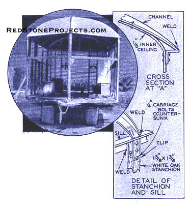
| The main chassis frame is of channel iron of 2 1/2" deep
as shown on the perspective drawing. Lay out the half-breadth dimensions
and chassis frame lengths in chalk on the cement floor of the garage. Have
the channel bent in the middle and at section B to coincide with the floor
plan. |
Here is the trailer as it appears before the ceiling
process has been started.
Note the roof in place.
|
|
| The bend in the middle is to a radius of 8", making a
sixteen-inch loop into which the trailer hitch is later fastened. |
|
All dimensions required for constructing the roof and
floor framework are given in the above diagram. Channel and angle iron
welded to the required forms constitute the chassis.
|
Get a restored copy of these vintage Cruisemite Deluxe
Travel Trailer Plans with 16 Pages of Enhanced and Enlarged Figures
and Illustrations and Searchable Text.
|
| Lay the main chassis frame on the floor, and using the
chalk outlines as a guide, weld in the cross members, the outside edge
angle iron as shown on the drawings and also the clips. These clips are
of the same material. 1 3/8" by 1 3/8" angle iron and about 4" long. When
this work has been completed, turn the frame upside down and weld in the
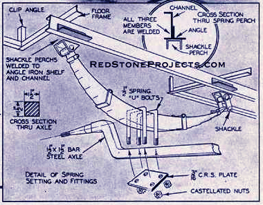
angle irons and the plates for the spring perches.
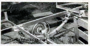
The spring used is a 28" Chevrolet truck type with 4"
shackles to allow a soft riding motion. Install these as shown then install
the axle and the wheels. |
|
Details of The Chassis Framing are clearly shown here.
The builder is cautioned not to alter the basic design of the craft except
for the stanchions which can be altered to provide the necessary headroom.
Pants of galvanized iron are attached over the wheels to improve the trailer’s
appearance. A commercial pressed wood material is used for side construction.
|
Get a restored copy of these vintage Cruisemite Deluxe
Travel Trailer Plans with 16 Pages of Enhanced and Enlarged Figures
and Illustrations and Searchable Text.
|
| It is suggested that you use a manufactured axle as this
will have the ends machined for the spindle, and upset. However, any blacksmith
can make you a steel axle with spindle ends for a pair of Ford V-8 front
wheels and upset them for the spring depth. The axle must be upset as the
bar must pass under the spring. This is not only good mechanical sense,
but in many states, it is law.
Make the standing jacks, as shown in the detail, next
so that the wheels can be fastened on the spindle, packed with grease,
and permanently installed. The frame completed, construction is started
on the roof. The frame for the roof is built as shown in the perspective
detail drawing. The roof beams are tapered on the top edge, either by weld-cutting
and grinding smooth, or hot shearing so that at a foot from either side
of the center line they taper to nothing at the ends. They can be bent
to an absolute crown of 14" or a coach crown whichever is desired. Weld
the beams, saw out for the 3/4" center or ridge pole channel and weld in
the stanchion clips. |
|
 |
|
Method of attaching the springs to the trailer
chassis.
|
| You will need 20 (twenty) 1 3/8" by 1 3/8" white oak
pieces planed four sides and finished to a maximum of 6" more or 4" Into
than 5 1/4", depending upon the height desired.
At this stage of construction procure about four or five
small C clamps and with the help of a few friends fasten the stanchions
at sections A and E of the chassis frame which has been jacked up level.
Install with 1/4" bolts, countersunk as shown, two transversely and one
plain longitudinally. You can bore through the clips easier if an electric
drill is used. Plumb the stanchions before final bolting, and then get
your friendly help to assist in hoisting the roof truss. This will set
on the erected stanchions. It also must be faired and bolted using the
C clamps to secure it while the bolting process goes on.
Now install the other stanchions. Put in those with the
clips, top and bottom, first. The extra, unclipped ones are for the window
frames and are attached with single bolts transversely into the longitudinal
face of the angle irons. At this stage of the game, you will find your
trailer in the same condition as a house frame with all the studding and
plates installed. |
 |
|
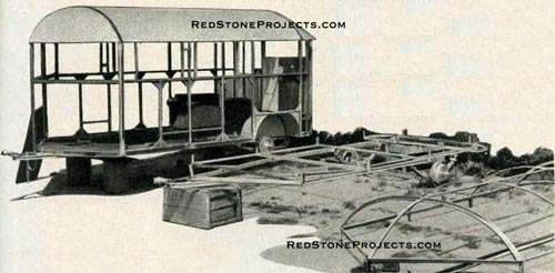
The original Cruisemite chassis is pictured here
with the roof and floor of a second one. The entire framework is welded
together to form a rigid chassis.
|
| Mount the middle body panel sills at the top and bottom
of the windows. These are exactly 4' from the top of the main chassis channel
to the top of the sills. The ends butt flush to the stanchions, and are
not let in. Plywood gusset plates are fastened with casein glue and bolt
to both the stanchions and the sills, with the outer faces coming flush
to the outside of the frame members to give backing to the paneling.
At this point the outer roof ceiling can be fastened on.
It is made of 3/16†pressed wood sheet, cut in convenient
panels and bolted with 1/8" machine screws into the ridge and channel members.
There will have to be occasional filler blocks placed in the angles for
the wood to bear against. Under the forward crown of the ridge pole or
center channel you will cut a 1/2" by 1 1/4" plywood carlin or former into
which you can later fasten the inner ceiling at this point. The curved
formers at the rear of the roof are. as the drawing shows, 3/4" by 1 3/4"
carlins. These are fastened to the channel with 16 or 14-gauge clips, and
bolted through. Use screws on the wooden members to fasten the pressed
wood down, starting at the center ridge, and working the panels down to
the edge.
After the outer portion of the roof is attached, wire
up the trailer for lights. There should be three circuits: one for 110
volts for use in parks and in the rear of your home, where you may want
to use the trailer as a spare bedroom. There should also be a set of wires
for the smaller voltage lights which can be run from the car battery upon
occasion, or from an independent generator set. The third set of wires
connects directly from car to running lights, which consist of a red tail
light with license plate, brake light, required by law in most states,
and the blue beam limit lights which insurance companies require if you
are to have coverage, and which in most states is required by law.
Plan the light outlets to suit the layout you have chosen.
About four 110-volt lights, and 6 to 12-volt outlets are sufficient. All
of the leads can be carried from the car to the trailer through a rubber
covered cable about 1/2" diameter, with five or six colored wires im-bedded;
enough to carry whatever circuit you want.
Since no car battery can stand the strain of more than
one overnight operation of trailer lighting requirements, a small A. C.
generator, powered by the car's motor should be used.
The pants for the wheels must be so fashioned that they
will have about 1" clearance over the wheels when the spring is fully depressed. |
 |
|
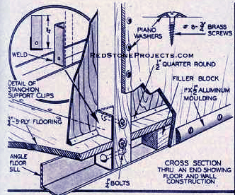
Manner in which the floor and stanchions are mounted.
|
| A good form for dimensions is given in detail. They can
be made up by any tinsmith out of 16 to 14-gauge metal, with rivets and
soldered seam and bent up flanges for fastening.
The trailer floor is built of 5-ply 3/4" fir panels bolted
through the filler blocks laid in the channel irons, with the heads counter-sunk
as shown in the detail plans. The clips are set in by rough saw cuts as
this portion of the floor is covered later by the ceiling.
Screw 1" half round between the stanchions with its bearing
face flush to the inside face of the stanchions. This will afford a hold
for the inner ceiling, which may be of 1/8" or 3/16" fir plywood, or pressed
wood.
Painting the framework is next. Use boiled linseed all
and turpentine, mixed half and half and kept in a double boiler to heat
it. Apply a coat of the mixture to all the outside wooden members and steel
work. Apply several coats to the wood to prevent dry rot.
Before putting on the outside ceiling, cover the roof
with grade A muslin, and dope it with airplane dope, after which the roof
is sprinkled with aluminum powder. |
 |
|
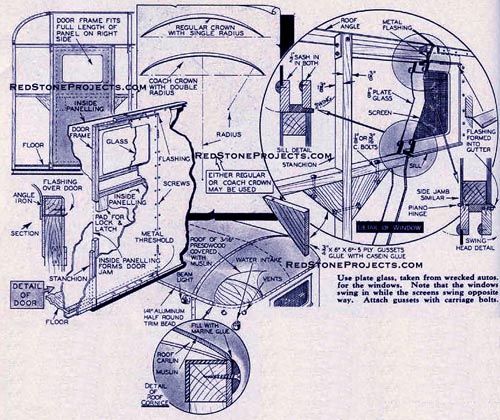
The door, like the rest of the side construction,
is built of pressed wood. The door frame is located on the right side of
the trailer and fits the entire length of he panel. Stanchions serve as
a frame for the door.
|
| The dope will hold the muslin to the ceiling although
a few tacks will be needed at the edges to temporarily hold the muslin
in place. Dope a few coats along the outer edges first, allowing a good
three to four hours in the sun for drying, then do the balance of the roof.
Now for the outside ceiling, which completes the work.
The water tanks and the piping for the shower have been put in, and you
are ready to finish up the job. This is merely a matter of doping the right
size panels to cover the frame, laying it on with good thick casein glue,
which holds like grim death, and prevents body squeaks. Use No. 8 3/4"
chromium head screws set in piano washers for this, spacing about centers
about 9". The seams of the panels should be joined on a jointer, and not
left rough as they come from the saw. It would be well to fill the seam
with casein as the panels go on, wiping off the outer edges immediately
with a damp rag.
On the bottom and at the seam where the roof meets the
side, put 1/2" oval aluminum stripping. At the roof, there will be an out
gage caused by the crown. Fill this with Jeffery's C quality marine glue,
applying hot from a squirt can. The can will pay out enough to make a full
seam. Keep a can of turpentine and a rag handy to enable you to avoid sticking
up the job. Marine glue must be put on hot, and all slop-overs wiped off
immediately. The heating can be done in a pot of boiling water. Keep the
glue away from all flames. A bead of glue should also be run around the
edges of the ventilators.
A few coats of good spar varnish are applied both inside
and out as there is nothing as weather resistant.
The skirt molding is put on, and the trailer is finished
except for the interior joiner work such as drawers and closet doors.
The hitch is a good ball and socket type. There are many
ways of installing these, but it has been proved best to do it, using both
welded joints, for rigidity, and bolts for security. You cannot afford
to have a failure occur here. The ball end and the details of this part
of the hitch must be taken from the car itself. Fasten the ball hitch to
the car frame, and NOT TO THE BUMPER. |
|
Any 2 Vintage Trailer Plans
$19.95 FREE Shipping |
|
Select 2 Vintage Travel Trailer Plans
|
|
|
