Free Shipping
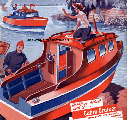
Build a 2 Berth Cabin Cruiser
Complete Plans For a Vintage Trailerable Cruiser
|
2 Berth Cabin Cruiser Plans
Build a Vintage Small Car Towable Cabin Cruiser
 |
PDF Format |
|
|
All Orders Processed
On a Secure Server
|
Price $12.95
|
|
Get a restored copy of these vintage 2 Berth Cabin
Cruiser Plans with 47 Pages of Enhanced and Enlarged Figures
and Illustrations and Searchable Text.
|
We will email these plans, to the address provided
with your payment, within 48 hours following receipt of your order.
|
|
| More Vintage
Boat Plans |
|
|

|
|
Build a 2-Berth Cabin Cruiser
By F. Hook
Part 1
Design Details and Commencing Construction
|
| THE craft was designed to explore the inland waterways
of this country and, possibly at a later time, tidal estuaries and serene
seas might be attempted.
The narrowest locks on British Waterways will take a boat
of 6 ft. beam, so this was adopted for the cruiser.
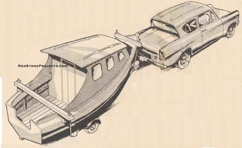
As the boat was to be towed behind a small family car,
careful consideration had to be given to the ease of loading and unloading
from the trailer as well as the capability of the car to tow the vessel.
It was estimated that the finished boat without the various living impedimenta
and outboard motor would weigh about 6 cwt.
A cabin was required for sleeping and in which to eat,
and this has a top on which sunbathers can recline. The design shows the
cabin extending back to Frame 4, the cooking and toilet arrangements being
restricted to the open well. By simple modification, the cabin could be
extended another section aft and the cooking arrangements and as small
toilet built into the additional section of cab.
Another arrangement would he to have small cabins fore
and aft, separated amidships by a small open well. |
|
The 2-Berth Cabin cruiser was designed to tow
behind a small family car.
|
|
| The Engine
As the boat was likely to be moved about ashore so frequently
it seemed better not to have the exterior encumbrances in the form of a
propeller and rudder necessary with an inboard motor. The inboard motor,
too, takes up valuable floor space. The obvious choice of motive power
was therefore the outboard motor.
This cruiser is a "displacement" type boat, i.e. it passes
through the water and not over the surface as would a speedboat. Because
of this important fact the boat has a basic maximum speed no matter what
engine is used. The marine engineer provides a simple formula which enables
the maximum speed of a displacement-type hull, such as this, to be determined.
The maximum speed in knots is equal to the square root
of the length of waterline, multiplied by 1.5.
Thus, as this craft is about 15 ft. waterline the maximum
speed will be square route of 15 x 1.5, or 5.8 knots.
Size of engine, then, is not of primary importance. The
power thrust imparted by the propeller is important and is closely bound
up with engine design, reduction gears and design of the propeller itself.
Bear in mind that a larger capacity engine running at a small throttle
opening will give a quieter and more economical cruising performance than
a small capacity engine running at full throttle. For cruising on inland
waterways, an engine such as the British Seagull Century, Anzani Super
Single or other manufacturers' engines of similar rating can be recommended. |
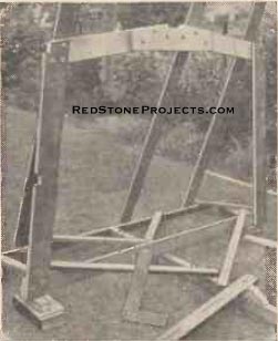
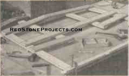
Figure 1. Frame 1 braced in
position on the building form.
|
|
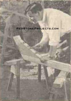
Figure 2. Bolting the stem
pieces together.
|
|
| Construction
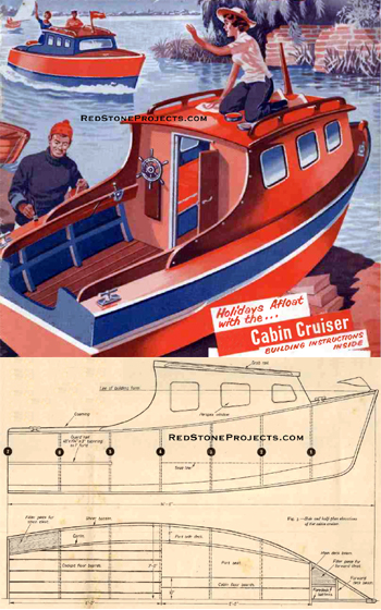
A side elevation and half plan of the cruiser are shown
in Fig. 3. These views give the principal dimensions of the hull and show
the disposition of the frames, battens, carlins, etc.
Materials Used
Whilst a list is given of the ideal timber to use for
the various parts of the boat, it is quite permissible for the constructor
to use other timber if he wishes. For example, in place of mahogany one
might use the cheaper timber Parana pine.
The stem, keel, hog and Frames should be of mahogany.
The chines, gunwales and stringers are of spruce. For the hull topsides
and bottom sides, mahogany plywood 5/16 in. thickness to B.S.S. IO88 specification
should be used. This plywood is particularly suitable for marine use as
it is extremely resistant to the effects of prolonged contact with water.
For the floors ordinary deal flooring, 1 in. x 6 in.,
may be used or alternatively Parana pine. This latter timber can be used
for most of the interior fitments.
The decks, cabin sides and roof are made from 1/4 in.
plywood to the B.S.S. IO88 specification.
The frames are glued and bolted together, using 2 in.
x 1/4 in. galvanized gutter bolts, with nuts and washers. For the glued
work in the boat, one of the well-known waterproof glues such as Aerolite
must be used. The skin is glued and screwed in place with 3/4 in. x No.
6 brass countersunk head screws. Some boat builders economize by using
galvanized steel screws instead of brass.
The Stem
From the diagrams it will be apparent that there are seven
frames (including the transom) and a stem to support the skin of the boat.
These items should be made first of all.
Details of the stem are shown in Figs. 2 and 4 and the
timber to use is mahogany, 3 1/2 in. x 2 1/2 in. finished sizes after planing.
The block used to bolt the two pieces together is cut from a piece of timber
about 2 ft. in length and 6 in. wide and finished to 2 1/2 in. thickness. |
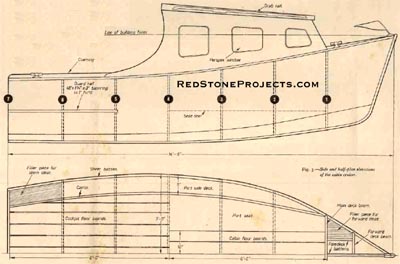
Figure 3. Side and half-plan
elevations of the 2-berth cabin cruiser.
|
| Fig. 4 gives the disposition of the first frame and the
building form. In arriving at the angles to which the various parts of
the stem should be cut it is better to set out the details of Fig. 4 to
full size on one of the sheets of plywood to be used for the hull covering.
The setting out of the timber is then very easy to achieve from this plan.
It will be noticed that the bolts holding the two parts
of the stem to the strengthening block are at right angles to these members.
This makes it necessary to cut four steps on the inside edge of the block.
The three parts may then be held in position with some large G-cramps to
test the fitting together of the surfaces. Very careful adjustment must
be made with a smoothing plane so that good mating is achieved between
all surfaces.
Brass bolts are specified for holding together the three
parts of the stem. It may be difficult to obtain such bolts and recourse
may be had to using galvanized bolts. An alternative method is to use some
1/4 in. brass rod which is threaded on each end and fitted with brass nuts
and washers.
The nuts on the outside ends must be countersunk into
the stem about 1 in. This may seem a lot, but later when the stem a trimmed
up to take the skin covering, a lot of wood has to be removed at these
points. Nothing is so annoying in the progress of the work than to have
to take out these bolts and deepen the hole in which the heads rest.
When all is bolted up satisfactorily in a dry state the
assembly may be taken down and glue liberally applied to all mating surfaces
and the stem than reassembled and set aside to dry.
Later the recess to take the hog may be cut and the stem
is then ready to set up on the building form.
Frame Construction
Dimensions of the frame, are given in Fig. 5.
When constructing the frames it is advisable to draw out
full-size plans of each frame on one of the sheets of plywood used for
covering the hull. The angles of the ends of the individual members can
thus be easily determined, sawn to shape and placed in position on the
plan. The assembly can he temporarily held together with some small G-cramps
whilst the 1/4 in. holes for the bolts are drilled (Fig. 6).
It is important to bear in mind the position of the chine
batten and arrange that bolt holes do not come too close to the notch which
takes these members.
When the frame is correctly assembled and bolted together,
it may be taken apart and glue applied to the joints. The whole assembly
is then bolted together again and finally placed in position on the full-scale
plan to check for accurate reassembly.
The tie beams or stretchers at the upper or deck end of
the side futtocks are only temporary, and at a later stage of construction,
when the cabin is constructed, these pieces are removed. Therefore, almost
any odd pieces of timber about 3 in. x 1 in. section can be used. |
|
Figures 4 and 5. Construction of the stem and frames
1 through 7.
|
Get a restored copy of these 2 Berth Cabin Cruiser
Plans with 47 pages of Enhanced and Enlarged Figures and
Illustrations and Searchable Text.
All Orders Processed
On a Secure Server
|
|
| If only new timber is available then of course these
pieces maybe used for interior fitments of the cabin later on.
When the frame is correctly assembled and bolted together,
it may be taken apart and glue applied to the joints. The whole assembly
is then bolted together again and finally placed in position on the full-scale
plan to check for accurate reassembly.
The tie beams or stretchers at the upper or deck end of
the side futtocks are only temporary, and at a later stage of construction,
when the cabin is constructed, these pieces are removed. Therefore, almost
any odd pieces of timber about 3 in. x 1 in. section can be used. If only
new timber is available then of course these pieces maybe used for interior
fitments of the cabin later on. |
| When the frames are assembled upon the building form,
it is important to note that the sides of the frames or the side futtocks
are on the end towards the stem and the bottom futtocks are towards the
stern. The floor support (20 in. x 5 in. x 3/4 in.) joining the bottom
futtocks is towards the stem.
As each frame is glued together it is important to wipe
away every trace of surplus glue with a damp cloth. This resin glue sets
glass hard and will ruin the edges of cutting tools if it has to be planed
away.
Whilst the frames are resting on the full-size plan it
is advisable to mark in quite clearly the position of the sheer batten
on the side futtocks.
It should be noted that the frames Nos. 1, 2, 3, 5, 6
and 7 will have to have the outer edges of the side futtocks beveled away
to correspond with the curve of the chine and sheer battens. Frames 1 and
2 are particularly sharply beveled and it is helpful to take off a good
deal of this bevel before assembling the frames on the building form. Final
truing of these bevels can only be done when all the frames are assembled
in place. |
|
Figure 6. Frame assemble temporarily cramped
together.
|
| The Transom
Frame 7 is called the transom and it is different from
the other frames in that it is covered with 3/4 in. plywood and a well
has to be cut in order to accommodate the outboard engine.
Additional battens have to be screwed and glued to the
transom frame in order to strengthen the cut-away part of the plywood covering.
Further filler pieces may then be secured on the other side of the frame,
thus making the transom twice as thick as the other frames. This additional
strength is important as rigidity is necessary to cut down vibration from
the engine throughout the boat to a minimum.
The building up of the transom should be carried out as
described, but the plywood covering is left until the other skin panels
are applied. The transom covering is put on last and will thus cover the
ends of the sheer and chine battens and the ends of the skin covering. |

|
Figure 7. Leveling up the building form.
|
|
| The Building Form
When the frames and stem are completed, attention may
be given to the setting up of these members on the building form. The finding
of a suitable site for building such a boat as this is always difficult.
A shed or other building with a level wooden floor is ideal. The frames
could then be held directly to the floor with screws and bracing battens.
Many readers will only be able to use the lawn at the back of the house,
and such was the case with the boat shown under construction.
Choose as level a site as possible and down the center
of it lay down a piece of 3 in. X 2 in. deal 16 ft. in length. By using
odd pieces of wood as packing under the 3 in. x 2 in., level up the batten
with a spirit level (Fig. 7). The batten should also be dead straight from
end to end and should be held in this position with some 1 in. x 1 in.
x 18 in. pegs driven into the ground on either side. Drive these pegs in
at different angles. This will key the batten to the ground so that it
cannot be pulled up by tension applied to the frames when fixing the keelson
and other longitudinal members. The pegs should be screwed to the batten.
Along this building batten, the position of each frame
must be clearly marked and a line squared across. At these positions odd
blocks of 3in. x 2 in. are screwed, against which the top stretchers of
the frame assemblies, may be screwed. All the frames are 24 in, apart.
First of all, erect Frame I in position and screw it to
the block on the building batten. Brace the frame with odd pieces of 2
in. X 1 in. so that it is vertical both lengthwise and transversely and
test down the center line of the frame with a plumb line or a spirit level
as used by a bricklayer.
The frame should also be at right angles to the building
form. This first frame must be very securely braced, as it must take quite
a bit of pushing and pulling during the course of building. |
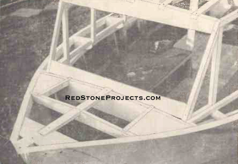
|
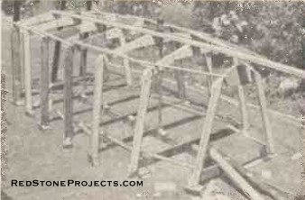
Figure 8. all seven frames in position.
|
|
| The other six frames are erected in place and securely
braced, vertical in two directions and square with the building form (Figs
1 and 8). |

|
Materials required for the hull.
|
|
Build a 2-Berth Cabin Cruiser
By F. Hook
Part 2
Finishing Off the Framework and Cladding with Marine
Plywood
|
| BEFORE the keelson can be fitted a housing must be cut
to accommodate it in the lower part of each frame assembly. The method
of determining the depth of these housings is illustrated in Fig. 10, which
shows how to set out a full-sized template for marking out the housings.
The template is made to the shaded area and applied over center line of
frame, adjusting until point x and y coincide with edges of frames. Next
mark out points A, B, C and D. Join the points and remove with saw and
chisel.
With frames numbers 1, 2 and 3 the housings have a slope
towards the stem, and a fair amount of fitting will be necessary to get
the keelson to have a proper bearing on the seats of the housings. A G-clamp
at each frame will help to hold the keelson down in place. It should be
unnecessary to have to steam the keelson in order to get it to take up
the correct curvature. Keep a watchful eye that cramping down, the keelson
does not distort the fixing of the frames or pull up the building form. |
|
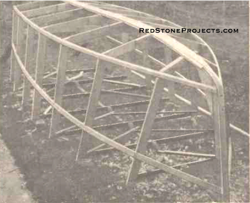
Figure 9. The assembled hull.
|
|
| Fitting the Stem
Remove the keelson from its position on the frames and
then proceed to fit the stem assembly on the building form, and resting
against the bottom futtock of the first frame. A shallow housing in the
form will keep the stem from slipping forward at that point. Make sure
the lower end of the stem is snug against the frame and make any adjustment
that may be necessary.
Finally, screw through the frame into the end of the stem
with two 2 1/2 in. x No 10 brass or galvanized screws. Be sure that the
recess cut on the end of the stem matches the housing cut in the frame.
Screw down to the building form the deck end of the stem. A couple of pieces
of 2 in. x 1 in., one each side of the stem and joined to the form will
help to keep the stern rigid.
When the stem is secure the keelson map be lowered again
and glued and screwed into its final position. Commence by securing at
the stem with two screws and then also put on a cramp to combat the leverage
exerted at this point as the keelson is pulled down into place. Be sure
to wipe away any surplus glue which may exude from the joints.
On the center line of the keelson set out the width of
the keel. From these lines the keelson must have chamfers planed to run
in with the slope of the bottom futtocks. The reader may find it helpful
to remove most of these chamfers before the keelson is finally secured
in place so that it may be held in a vice. But final planing must be done
with the keelson in place.
On each pair of bottom futtocks, each side of the keelson,
a water-way must be cut out. These ways should be fairly large as small
holes very quickly get stopped up with odd matter which finds its way to
the bottom of any boat. |

Figure 10. Marking out recess
for hog in frames.
|
|
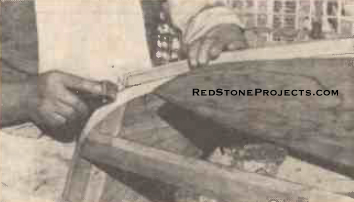
| Fitting the Chine and Sheer Battens
These four members are made from some 1 3/4 in. x 3/4
in. spruce which should bend round into the correct curvature without resort
to steaming. Slots are cut in the frame assemblies as shown in Fig. 1.
to take these battens.
At the stem the batten is sawn to butt against the stem
and is then held in place with 2 1/2 in. x No. 10 brass or galvanized screws.
A little practice is necessary to hold these battens in approximate place
against the stem and to saw the correct bevel, therefore it better not
to screw the battens to the frames until a correct fitting has been established,
but to hold the batten in place with cramps.
With the chine battens cramped in place look along the
line of the batten to make sure that a smooth curvature is obtained. If
there are any irregularities, slight adjustments to the notches may be
necessary. It is very important to get a smooth curve at this juncture,
even if the notch has to be enlarged a little up or down the futtock. |
|
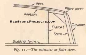
Figure 11. The cutwater, or false stem.
|
|
| Sheer Battens
The sheer battens are also let into notches in the side
futtocks of the frames. The positions of these battens can be seen in the
frame plans (Fig. 5) and they should have already been marked out on the
frames. Here again it is important to get a smooth line to the batten.
Saw the forward ends of the battens at an oblique angle
to butt against the stem. The assembly of the hull will now look as in
Fig. 9.
Next the bottom and side stringers must be fitted. The
former run parallel with the keelson from frame 1 to the transom. The latter
fit against the stem and run through to the transom (Fig. 13).
When notching in these members at frames 1, 2 and 3 remember
to let in the stringers flush with the rear edges of the frame. Later the
protruding pieces at the bow side will have to be planed down during the
fairing off procedure.
Close reference to Fig. 9 will show that a bevel has been
worked on the top of the stem and that the chine batten runs in with this
bevel. The bevel also runs down the entire length of the stem to the sheer
batten although this has not been completed in the photograph. |
|
Figure 12. Details of the bottom stringer.
|
|
| The Keel
The keel is a piece of timber 1 3/4 in. x 3/4 in. finished
size. The keel ends 1 in. overlapping the joint of the front member of
the stem assembly as shown in Fig. 11. and in Fig. 13. This keel is continued
up the front of the stem with a false stem or cutwater which is screwed
into position after the plywood panels have been glued in position and
cleaned off flush with the stem. Thus, the front edges of the panels are
protected by the cutwater. A small filler piece will be needed to join
the cutwater with the keel, shown in Fig. 11.
From frame No. 1 the keel commences to taper in towards
the stem to a final width of 1 1/4 in. When this has been worked the keel
may be cramped into place and screwed down. Delay glueing and screwing
for the time being as it may be helpful to be able to remove the keel during
the final fairing off of the frames. |

|
Figure 13. Details of the keel assembly.
|
|
| Fairing Off
This process may appear to be rather tedious, but it must
be done thoroughly so that the plywood panels bed down evenly on the various
other members. The first three frames will require the most work as they
have sharply beveled sides towards the stem.
The side and bottom futtocks must be planed so that their
edges run in smoothly with the various longitudinal battens. The bottom
edge of the chine battens must be beveled to run in with the bottom futtock
edges (Fig. 14).
The stem must be beveled so that the front edge is the
same as the width of the forward end of the keel (1 1/4 in.). A slight
adjustment to the butt joint of the chine and sheer battens may be necessary
to run in with these bevels.
An iron smoothing plane and a Surform, or Stanley file
or plane are the ideal tools for this operation. In fact, this is an almost
indispensable tool for the boatbuilder. From time to time the work must
be tested with a lath which can be laid across the edges being planed. |
|
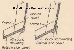
Figure 14. Joint of plywood
skin at chines.
|
|
| Fitting the Panels
There are four, bottom-side panels and four top-side panels
and these are out from sheets of marine plywood 8 ft. X 4 ft. The cutoffs
left over from these panels are used to make the seat tops, etc. at a later
stage of construction.
It is advisable to commence with the fitting of one of
the forward panels even though these are the most difficult to fix. Large
sheets of brown paper are glued together to give enough area to cover one
panel. The outline of the required shape is obtained by placing the paper
over the frames and rubbing the thumb along the edge of the chine to the
stem, up the forward edge of the bevel on the stem, and then along the
join between the keel and the keelson to frame 3 and down the edge of that
frame.
The shape of the panel may then be cut out, but leaving
an additional 1 1/2 in. beyond the chine line to allow for the subsequent
fitting of the top-side panel to this panel.
Note that this bottom side front panel ends at the third
frame and provision must be made to strengthen this butt joint with the
aft bottom-side panel. To provide extra bearing for this glued joint, additional
strips of 1 3/4 in. x 3/4 in. timber can be glued and screwed to the bottom
futtock of the frame.
Alternatively, a 3 in. strip of the panel plywood can
he let in flush into the keelson, chine and bottom stringer thus providing
a good bearing for the butt joint of the panels when glued and screwed
into position.
First of all, cramp the stern end of the panel into place
at Frame 3 using G-cramps at the keelson and chine. Bend the panel down
into position and cramp where possible.
If the builder feels that undue pressure is needed to
hold the panel down in place at the stem, the plywood can be made more
pliable by the application of rags dipped in boiling water and applied
to the outside surface of the plywood. If the timber is thus wetted it
must be cramped in place and allowed to dry until next day before being
glued in place.
When the cramps are removed, the plywood will have taken
on a permanent curve to the shape required so that little force is then
needed to glue into place.
It is important to get a good fit up to the edge of the
keel and a bevel most be planed along the edge of the plywood for this
purpose. A small lap-over at the stem can later be planed away when the
cutwater is fixed. Keep the lap-over at the chine for the purpose of making
the notched joint to the top-side panel as in Fig. 13.
When one is satisfied that there is a good fit, mark with
a pencil round on the underside of the panel the shapes of the frames,
the keelson, the stem, etc., and then remove the panel for drilling for
the seeming screws. The screw holes are drilled with a 9/64 in. drill and
are spaced 3 in. apart. Between frame and the stem and along the stem these
holes should be close to t 1 1/2 in. centers. To speed up this work an
electric drill is indispensable. The holes should also be countersunk so
that the heeds of the 3/4 in. X No. 6 brass counter-sunk head screws will
be below the surface. Subsequently, the holes are stopped.
When all is ready for the final application of the panel,
prepare the Aerolite 300 glue, which, being waterproof, is an ideal adhesive
for all boat building work. Full instructions for the use of this glue
are given with every pack.
The glue is first of all applied liberally to all bearing
surfaces of the chine, stem, keelson and frame, etc. The hardener is applied
to the areas within the pencil marked outlines on the inside of the plywood
panel.
Place the panel in position and first of all hold by one
or two screws at widely spaced intervals to ascertain that it is correctly
positioned. When all is well, proceed to screw down all round the panel.
When the screwing is completed wipe away all surplus glue which may have
oozed out of the joints.
The other forward bottom-side panel is fitted next, but
it must not be assumed that it is exactly the same pattern as the previous
panel and it may be necessary to make a new paper pattern.
When the first and has been fitted the permanent fixing
of the keel should no longer be delayed. It should be liberally glued and
then screwed into place with some 2 in. x No. 10 to galvanized steel screws.
Note the termination of the keel in Fig. 11 as overlapping by 1 in. the
joint between the two parts of the stem. |

|
Figure 15. The finished cutwater.
|
|
| After fixing the two bottom-side forward panels, the
fixing of the two aft bottom-side panels will be a much easier task as
there is little bending of the plywood. Be sure there is plenty of glue
in the but joint of the after panel with the forward panel.
When the glue has dried out on all four panels the edges
of the panels may now be trimmed up flush with the chine battens and the
frame of the transom. One important point must be made. From the stem of
the first frame the forward bottom-side panels are not trimmed flush but
are left overhanging as shown in Fig. 12. Thus, the joint between the top-side
panels and the bottom-side panels is shown in Fig. 14 for the two positions,
fore and aft of frame 1.
Securing the Top-side Panels
The next task is the fitting and fixing of the top-side
panels. Commence with the forward panels. It is possible to dispense with
the use of a paper pattern for this work. Hold the plywood in place against
the side of the boat with a pair of G-cramps and mark the position of the
notched joint already mentioned.
Saw out the piece required to make a recess for the bottom-side
panel and bevel this so that the new edge of the panel will fit snugly
against the bottom-side panel overhang. Aft of the notched joint allow
a small overlap at the chine for trimming up later. Allow also a small
overlap at the stem and along the sheer for subsequent cleaning up.
The join between the fore and aft top-side panels is arranged
between frames 3 and 4. As seating for this join, filler pieces of wood
1 3/4 in. x 3/4 in. are let in between the battens and another piece is
screwed on the inside of the battens to which also the filler pieces are
glued and screwed.
The Transom Panel
The last part of the skin of the boat is the 2/3 in. plywood
transom panel. This panel is cut to shape approximately and with a liberal
application of glue it is then screwed in position. The screws to use are
1 1/2 in. x No. 8 countersunk head brass. Often the transom is not painted
in the same way as the rest of the hull but is left in natural color and
varnished. If this is done then the heads of the screws are not deeply
countersunk but only sufficient to let the heads be pulled in flush with
the surface of the transom. No stopping is used. To comply with the best
marine practice be sure that all slots in the screw heads are all pointing
in the same direction.
The False Stem or Cutwater
From the end of the keel the edges of the plywood skin
are planed down flush with the stern. A false stern or cutwater is now
fitted to cover the stem and these edges.
As the cutwater may come in for some hard knocks when
the boat is in use it is helpful to be able to renew this pad without difficulty.
Hence, it is not glued in place, but instead a sealing layer of Seelastic
is used and the cutwater is screwed in place with same 2 in. x No. 10 countersunk
head galvanized steel screws. Some holes are drilled with a 3/8 in. twist
bit to let the screws into the false stem. These holes may be stopped afterwards
with dowel rod plugs or other forms of stopping.
Between the lower end of the false stem and the end of
the keel is a small space which has now to be filled with a small filler
piece, which is worked to the curve of the keelson and to be a snug fit
between the keel and the cutwater. It is finally glued and screwed in place
with two screws.
It is advisable to leave the filler piece and the lower
end of the cutwater a little full, in order that they may be worked up
to the final shape when they have been secured in place with their screws
(Fig. 15).
The Rubbing Strips
A rubbing strip (Fig. l6) is fitted along the chines and
is made from some 1 1/2 in. half-round molding. These strips serve a double
purpose because they also serve to seal the joins of the top-side and bottom-side
panels. A sealer such as Seelastic is applied under the strips before they
are screwed in place. Well countersink the heads of the screws and fill
the holes.
To seal the forward part of the panel abutments forward
of the point where the notch joint is made in the panels, a shorter strip
of molding may be applied here and not carried right aft.
Additional rubbing strips are screwed to the bottom sides
of the cruiser along the line of the battens between chines and keel (Fig.
16).
Guard rails are also required reaching from the transom
to frame 5, as this part of the hull is very vulnerable in locks and at
moorings. The rail is 26 in. in length, 3 in. at the transom and tapering
down to 1 in. at the other extremity. The rails are screwed well to the
transom and fames 5 and 6.
Last Stages Before Turning Over
The boat is now ready for turning over (Fig. 16) except
for the final finishing off of all surfaces with various grades of glasspaper.
All screw holes should be stopped with Plastic wood or marine stopping.
If the head of a screw seems at all near to the surface take it out and
re-countersink the hole. |
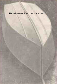
Figure 16. The boat ready
for turning over.
|
|
| When the stopping is dry, a final rubbing down will be
needed. The skin is now ready for the first priming coat of Paint. These
priming coats, of which there should be three, should be pink priming well
thinned down with turps. A light rubbing down should take place between
each coat.
Two undercoats of the appropriate shade should follow.
The surface is then ready for the final application of top coat enamel.
For this paint work, one is well advised to choose from the wide range
of paints specially made for marine use. On the other hand, good service
has been had from good quality household paint as used for exterior woodwork.
Work on the Boat Turned the Right Way Up
Two persons can now quite easily turn over the boat after
all ties have been broken with the building form which has, during construction,
been pegged to the ground.
The first step now is to support the keel on a level site
and it is quite satisfactory to stand it on the 3 in. X 2 in. building
form, which is still secured to the ground. The boat being level longitudinally
the procedure now is to support it near the chines at two or three frame
positions with blocks and wedges so that it is level transversely.
In order to preserve the interior of the boat from the
effects of damp to which it will continually be subjected its necessary
to give the interior two or three coats of clear Cuprinol. At a later stage
this can be painted over. Be careful to apply the Cuprinol liberally to
the end grain of any timber and down in cracks and crevices which may be
found.
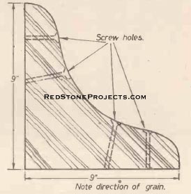
Transoms Knees
Three knees are used to strengthen the joint between the
transom and the keelson and bottom-side battens. The knees also help to
cut down vibration in the transom when the motor is running. The knees
are cut from some 1 1/4 in. mahogany or oak. Be careful of the direction
of the grain and this is shown clearly in Fig. 17.
The fit against the bottom members and the transom must
be accurate, and after sawing the angle of the knees to a right angle they
can be tried in place and fitted by planing the edges with a smoothing
plane.
The knees are glued and screwed to the transom and bottom
members with some 2 in. x No. 10 galvanized steel screws. The screws will
have to be recessed into the knees so that the threaded part of the screws
protrudes about 1/2 in. to 3/4 in. These holes can be drilled out with
a 1/2 in. twist bit first of all and then the hole is followed through
with 3/16 in. twist drill.
Whilst doing this work it will be necessary to get inside
the boat and whilst it is possible to walk on the panels it is likely that
unnecessary strain may be thrown on the joints if this is done, it is therefore
advisable to keep on the battens or keel as far as possible. |
|
Figure 17. The Transom knees.
|
|
| The Floorboards
The fitting of the floorboards should be the next task,
starting with the floor of the cockpit. The flooring is made from 1 in.
x 6 in. floorboards, planed all round. Alternatively, 1/2 in. exterior
grade plywood could be used.
The floor must rest on three filler pieces of 3/4 in.
timber cut and secured as shown in Fig. 18. These filler pieces are fitted
to frames 4, 5 and 6 and a support of 1 3/4 in. x 3/4 in. is screwed across
the transom, and will need to be in several pieces to fit round the knees. |
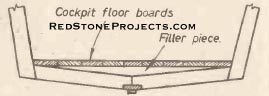
Figure 18. Filler pieces supporting
the cockpit floor.
|
|
Build a 2-Berth Cabin Cruiser
By F. Hook
Part 3
Concluding Floor Details and Framing for the
Fore deck and Cockpit Coamings
|
| Continuing Floorboard Details
THE height of the supports must be lined up so that the
floorboards do not rock, and this might be tested with a straight-edge
of one of the floorboards. Note the outside board on each side will have
to be shaped to fit the curvature of the hull.
Access is often wanted to the bottom of the boat so that
it is advisable to make the center three boards joined together with an
odd piece of batten at each end and in the center. The outer boards can
be screwed down with some 1 1/2 in. brass screws. Do not cramp up the boards
tightly against one another. Instead, leave a gap which can be gauged the
same for each board by using a spacer cardboard when screwing down.
Before finally screwing down the floorboards it is advisable
to paint the underside of the boards and the bottom or bilges of the boat.
For the latter surfaces which are almost always wet or damp a bitumastic
paint might be thought more suitable than the customary oil paint. This
should be applied up to the chine batten; above this point oil paint should
be used. Be sure to clean out the bottom of the boat before painting, a
vacuum cleaner will be most useful in removing sawdust from crevices. |

|
Figure 19. Section of the cabin floor.
|
|
| The Cabin Floor
This floor is composed of four pieces of 1 in. x 6 in.
flooring. As it need be only a little over 20 in. wide it can be fitted
directly upon the 20 in. frame stretcher. Thus, the floor level will be
lower than that of the cockpit. This is helpful in providing more cabin
head room.
In order to accommodate the full width of the floor it
may be necessary to cut small notches in frames 2 and 3 (Fig. 19).
At Frame 1 the two outside boards will have to be tapered
in to about half their width at their extreme forward ends. The two outer
planks can be screwed down in position after painting, but the two center
planks should be battened together and made to lift out to give access
to the bilge, as with the cockpit boards.
Side Deck Carlins
The carlins for the side decks are next to be considered
and these are supported by knees secured to the top ends of the frame members.
It is now necessary to consider the removal of the stretchers across the
ends of the frame members as these should have been left in place during
the work on the floor. In order that there may be no likelihood of the
gunwale losing its shape during the fitting of the carlins temporary stretchers
may now be bolted across the frame members about 6 in. below the gunwales
which will not be so much in the way as those at the extreme ends of the
frame members. Thus, remove one stretcher at a time and shorten as necessary
and bolt on lower down. |
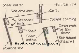
Figures 20 and 21. Longitudinal members attached
to side deck
knees and carlin ends at frame 1.
|
|
| Refer to Fig. 20 and note that the knees are 3 1/2 in.
wide and are sawn from the ends of the side members of the frames when
the stretchers have been removed.
The knees slope upwards towards the center of the boat
and this slope should correspond with the slope on the top edges of the
transom, i.e. there is a rise of 3 in. on the center line. It is advisable
to start with frame 6 and check the slope with a straight-edge as well
as sighting from the transom line. Thereafter, the slopes at the other
frames may be all done by sighting from the stern, securing with one nut
and bolt and tapping up or down as required to get the correct slope and
then drilling the other bolt hole and securing. No knees are required for
frame 1.
Cutting the Knees to Length
Before attending to this operation be sure that the boat
is level across its width by placing a straight-edge across from gunwale
to gunwale and resting a spirit level on it. Wedge up the chines until
dead level is indicated. |
|
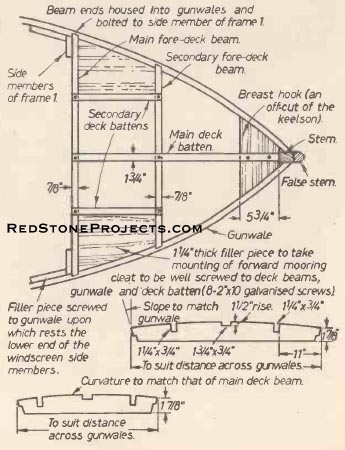
Figure 22. Details of the fore deck.
|
|
| From points 8 in. from the outside edge of the gunwale
a vertical line is drawn to indicate the end of the knee (Fig. 20). A variation
is to be found at frames 1 and 2. At frame 1 there is no knee but a notch
is sawn and chiseled in the vertical frame member to take the end of the
carlin (Fig. 21). The length inwards at frame 2 will be about 5 1/2 in,
but is best checked by springing the carlin into position and securing
on the top of the knees with G-cramps and scribing the lines for the recess
to be cut in each for the carlin. It should be noted that the line at which
the cut is made will not be square except at frame 4 and the carlin in
position will help to get the correct angle easily.
Two housings will have to be sawn in the transom for the
extreme ends of the carlins. These will need to be about 3/8 in. in depth.
The carlins can now be screwed into place with brass screws.
The Shelf
Two similar members to the carlins are fitted underneath
the knees to the side members of the frames (Fig. 20). The object of the
shelf is to give support to the knees as well as to generally stiffen up
the gunwales of the boat. Remember that the side decks have to take the
weight of the crew scrambling alongside, and, of course, the knees take
the weight of the cabin as well as any passenger who might be reclining
on the roof.
These members are notched into the frame for 1/4 in.,
and are then securely screwed in position with 1 1/2 in. x No. 8 brass
screws.
The Fore Deck
The fore deck is supported by two deck beams and the breast
hook, details of which are given in Figs. 22 and 23. As these beams are
called upon to bear a fair amount of weight they may be notched into the
sheer battens. They are then screwed into position from outside the boat
with some 2 in. x No. 10 galvanized screws well countersunk in the plywood
skin. The top curvatures of these members should be the same.
The central deck batten is housed into the main deck beam
and the secondary beam. A small housing may be necessary in the breast
hook to take this batten. Two smaller deck battens are also fixed across
the two deck beams.
At this stage one must bear in mind the requirements of
a strong point at which to fix the mooring cleats at a later time, and
it is better to do this before the deck coveting in fixed. These filler
pieces are shown in Figs. 2 and 23, and should be of some 1 1/4 in., or
1 1/2 in. thick Parana pine or oak. They should be carefully fitted to
all four members to which they are attached.
Finally, the filler pieces are glued and screwed in position.
Any slight protrusions above the level of the beams can be removed with
a smoothing plane.
This completes the fore deck except for covering which
operation (Fig. 24) is better left for the time being whilst attention
is now given to the construction of the cabin framework. |
|
Figure 23. The fore deck framing.
|
| Cockpit Coamings
The cockpit is lined on the inside of the carlins by the
coamings (Figs. 20 and 24). These members are made from timber 5 3/4 in,
x 3/4 in. If they are to be painted at a later stage, they can well be
made of Parana pine. On the other hand, mahogany coamings look very fine
and are best left natural color and varnished. This arrangement would look
well with a natural mahogany transom. The coamings are screwed to the ends
of the knees and the carlin. They reach from the transom, into which they
are housed, about 1/4 in. and end at frame 4.
It is of interest to note in passing that at this stage
the boat could very rapidly be completed for use as an open run-about.
The fore deck and side decks could be finished and coaming run the full
length from frame 1 to the transom. Some cross seats could be improvised
and the boat is ready for painting. It is possible for the constructor
to use the boat like this and to convert it later to the full cabin cruiser
design with very little trouble. |
|
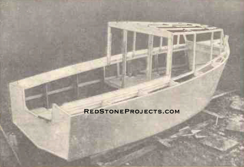
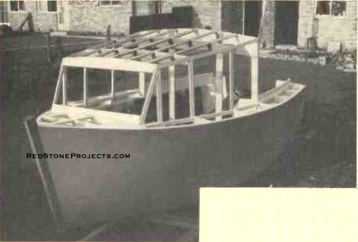
Figure 24. This stage shows the cabin framing
and cockpit coamings.
|
|
|
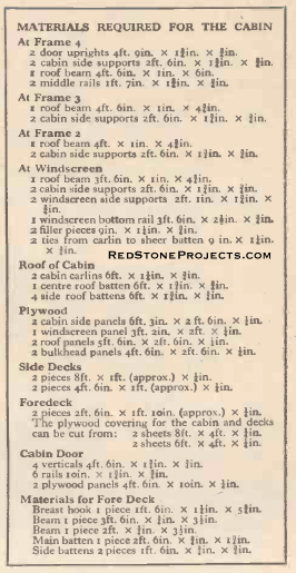
Materials Required for The Cabin
|
|
Build a 2-Berth Cabin Cruiser
By F. Hook
Part 3
Concluding The Construction
|
| IT is better to commence work on the cabin of the boat
at the main cabin bulkhead at frame 4 and work forward to the windscreen.
This bulkhead is framed up with four vertical members and a cabin roof
beam (Figs. 25 and 28). |
| The two outer vertical members are secured first of all
to the ends of the coamings around which they are notched. Ensure that
the inwards slope of these members is identical. The two members which
form the door frame must be exactly vertical when the boat is precisely
horizontal across the beam and also should be checked to ensure they are
parallel. |
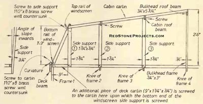
Figures 25, 26 and 27. Sectional views at frames
4, 3 and 2 looking forward.
|
Get a restored copy of these 2 Berth Cabin Cruiser
Plans with 47 pages of Enhanced and Enlarged Figures and
Illustrations and Searchable Text.
All Orders Processed
On a Secure Server
|
|
| The cabin beam rests on top of these four members to
which it is secured by four plywood gussets screwed on the inside of the
bulkhead across the joints. The door frame members are screwed at their
lower ends to the lower members of frame 4.
At frames 3 and 2 vertical members are secured to the
knees and carlin and sloping in at the same angle as those of frame 4 (Figs
26 and 27). This can be judged by sighting from the cockpit along the edges
of the bulkhead. These members are 1 3/4 in. 3/4 in. and the vertical length
is better left a little full at first. The roof beams should be clamped
to their top ends and adjusted into position by sighting along the top
of the cabin beams.
The curvature of all the roof beams should be the same.
Consequently, when the curve has been set out on the bulkhead beam the
other beams can be marked out from this one.
Another point of importance concerning the vertical members
at frames 3, 2 and windscreen position is that they should also be parallel
to the bulkhead frame when viewed from the sides of the boat. That is to
say they should all be parallel to one another.
The vertical member at the windscreen position is screwed
only to the carlin, which is perhaps a weakness, consequently a strengthening
piece of 1 1/4 in. x 3/4/ in. fixed across from the carlin to the sheer
batten at this point to give additional support.
The sloping windscreen side members do not rest upon the
carlin (Figs. 29 and 31), but upon a 9 in. piece of carlin timber screwed
against the carlin. For the time being do not proceed with the windscreen.
Check the alignment of the roof beams and then scribe
their positions on the side members at frames 2, 3 and 4 and cut out a
notch upon which the beams can rest (Fig. 28). Screw the beams into position. |
|
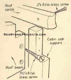
Figure 28. Details of junction of roof beam.
Roof carlins, and cabin side supports.
|
|
| The Cabin Carlins
The two cabin roof carlins should now be fitted. At first
cramp a light piece of timber (1 1/2 in. x 1/2 in.) along the ends of the
beams to get the slope required to the top ends of the vertical members.
Then trim off these waste pieces.
Now mark and cut notches in the ends of the deck beams
to take the carlins, 1 1/4 in. x 3/4 in. These carlins are screwed into
the ends of the beams. The forward ends of the carlins will mark the height
and slope of the top ends of the forward side supports. Saw off waste and
screw the carlins into the top of the supports.
The windscreen (Fig. 31) can now be completed by screwing
the sloping members in position and then fitting the top rail with a curvature
to correspond with that of the other deck beams. All this work may be done
with neatly made butt joints provided they are well glued with Aerolite
glue and screwed up tightly. It is important to keep an eye on any likely
points at which rain may penetrate and to be sure that they are well sealed
with either glue or Seelastic. |
|
Figure 29. Details of cabin side structures.
|
|
| Roof Battens
The roof has five battens. The central one is 1 3/4 in.
x 3/4 in. and the others are 1 1 /4 in. x 3/4 in. The central one is wider
to make a good jointing surface for the two pieces of plywood with which
the roof is covered.
These battens are notched into the roof beams and screwed
into position (Fig. 26).
Now fairing off the roof members can be undertaken with
a smoothing plane. Make sure all screw heads are well counter-sunk to save
any damage to the plane blade. |
|
Figure 30. Photo taken during cabin construction.
|
|
| Carlin Filler Pieces
Applied to the side-deck carlins in between the vertical
members of the cabin framework are some pieces of 2 in. x 5/16 in. thickness
plywood. These pieces form a ledge against which the lower edges of the
side panels of the cabin can be screwed. They also provide a bearing surface
upon which to put the Seelastic sealing compound.
The Side Decks
The upper structure of the cruiser is now ready for covering
in with 1/4 in. thick plywood. The layout of the various panels is given
in Fig. 32, but it is to be noted that these sizes are only approximate.
Commence by fitting the fore-deck (Fig. 31) which consists
of two triangular panels. The top of the stem should be trimmed away flush
with the sheer battens. The top of the false stem may be left for the time
being and later it may be rounded or shaped to suit the constructor. It
is essential to get a good fit of the foredeck against the lower windscreen
rail. It is helpful if the panels are held in place with just one or two
screws at first to ensure a good fit before using sealing compound. |
|
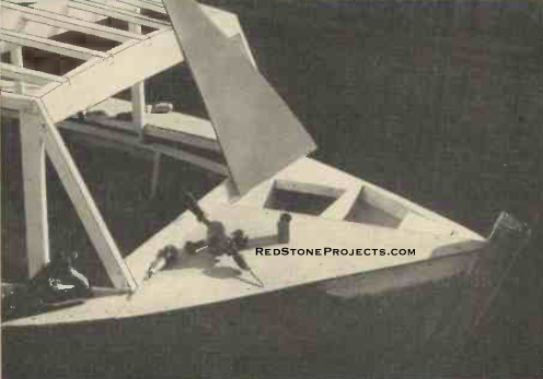
Figure 31. Fitting the fore deck.
|
|
| When all is ready Seelastic is thinly spread upon the
edges of the deck beams, battens, sheer battens, etc., and then the panels
are put into position again and screwed down with screws at every 4 in.
Use 3/4 in. No. 6 brass screws. If the decks are to be left natural color
and varnished then the screw heads are best driven in just flush with the
surface. If the decks are so be painted then the screws may he sunk in
a little and the holes stopped.
Each side-deck comprises two panels. The shorter forward
pair of pieces must butt neatly against the ends of the foredeck and against
the carlin filler pieces. The aft ends of these panels reach to frame 3.
In order to provide a wider bearing surface at this point for the joint
of the two panels it is advisable to screw on extra bearer to the knees
at frame 3 as well as at frame 1.
The two stern-side deck panels butt against the forward
two and against the cockpit coamings. Trim off any overhang at the transom
and along the gunwale line. The outer edge of the side-deck panels can
finally be sealed over with a length of 1 1/2 in. half-round moulding screwed
and sealed from bow to transom. |

|
Figure 32. Layout of plywood panels for the
superstructure.
|
|
| The Windscreen and Cabin Side Panels
Roughly trim these panels to size and mark in lightly
any members of the cabin framework and then give consideration to the arrangement
of the openings for the windows.
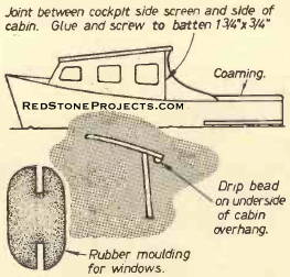
These windows are of 1/8 in. Perspex and are held in place
with rubber moldings similar to those used for car van windows. It is necessary
to get the correct molding for the thicknesses of materials being used.
A typical cross section of rubber molding is shown in Fig. 35. Remember
to avoid sharp curves in window openings when using such moldings as it
is difficult to fit them to very sharp curves. A minimum curve of 2 1/2
in. radius is suggested. |
|
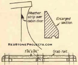
Figures 33 and 34. Weather strip over cabin
door and grab rail.
|
|
| In passing it is of interest note that instead of a fixed
windscreen window panel the constructor may wish to contrive a window which
hinges outwards as on an old-type car windscreen. In fact, it is possible
to use salvaged car windscreen for this purpose.
Another reason for such an opening window is that it provides
an emergency exit forward should the cabin door get jammed or in the case
of fire in the after well. A grim thought but at least one for which it
is as well to make provision. Needless to say, one or two small car-type
fire extinguishers should form a part of the gear in the boat when it is
in use.
Assuming then that a fixed windscreen panel is to be used,
fit it in place nuking a good fit against the fore-deck on the bottom edge.
Trim off level at the roof beam and the side uprights.
Fit next the two bulkhead panels. A small filler piece
will be needed over the top of the door. In addition, at that point, it
is advisable to fit a strip which will protrude over the top of the door
to keep rain from running in (Fig. 33).
The side panels are now fitted. They must make a good
fit against the side decks. Final trimming off of the two ends may he delayed
until the panels are screwed in place. Sealing compound is used again under
all surfaces which butt together to give a water-tight joint. The rear
ends of these panels most be left overhanging about an inch in order to
screw against a jointing strip of 1 3/4 in. x 3/4 in. to which is also
screwed the side screen of the cockpit (Fig. 35). |
|
Figure 35. Cockpit side screen and rubber molding
for window.
|
|
| Finally, the roof panels are secured in place. The edges
may be trimmed back flush with the sides and ends and a molding be screwed
over the joint to make a waterproof seal. Alternatively, an even more weather-proof
arrangement can be made by having small overhanging eaves all round, rather
more overhang should be provided at the bow end for effect. The underside
of the overhang can be reinforced with some 3/4 in. half-round molding
which will also act as a drip beading (Fig. 35).
A length of 3/4 in. quarter round molding is screwed and
sealed along the side decks against the cabin sides, the coaming and the
windscreen. This sealing strip must be put on very carefully and sealed
so that there is no possible chance of water penetrating below decks in
the worst of weather. This is the most vulnerable point for leaks in any
craft, such as this.
The Grab Rails
These are essential fitments for the roof of the cabin.
They are to provide hand holds when walking along the side decks and are
useful to prevent such articles as mops and boat hooks from rolling off
the roof of the cabin.
The rails (Fig. 34) are in two parts and are of 1 1/4
in. x 3/4 in. material, neatly rounded to be comfortable to hold, screwed
to the cabin roof battens with a spacer or similar material.
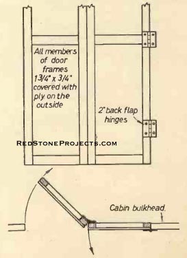
The Cabin Door
The cabin door (Fig. 36). is made of two 10 in. wide doors
which are arranged to fold in half and thus take up less room in the cockpit
when opened. |
| The frames are constructed with the use of half-lap or
mortise and tenon joints. The plywood covering is held in place with brass
nails or screws as well as glue.
Brass backflap hinges are used. They are better than butt
hinges as they may be laid flat on the frames and thus give a wider bearing
surface.
A small bolt top and bottom on the inside of one half
of the door will secure it, and a handle and lock of a suitable kind on
be fixed to the other half of the door.
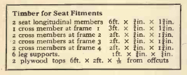
Cabin Seats
The interior of the cabin can be fitted up to any requirements
of the reader. In the present design the author kept a parallel gangway
of 20 in. width down the center of the cabin. This makes the seats taper
off at the bow, but nevertheless wide enough to sit on. See Figs. 25, 26
and 27.
Supports for the seats are of 1 3/4 in. x 3/4 in. timber
and the seat tops can be offcuts from the panels used for the skin of the
boat. These will have to be shaped to the curvature of the boat and slots
cut to fit around the frame members. To provide more bed space it may be
necessary to carry pieces of plywood to fit across from one side to the
other of the gangway. The seats can be covered with foam rubber cushions
which are excellent in that they do not retain moisture in the same way
as other types of mattresses. |
| The spaces under the seats are valuable for storage purposes
and they can be made more we of if the front of the seat is covered in
to prevent articles from falling forward. The floor should also be lined
to prevent small articles from falling down into the bilges.
Rubbing Strips at Stern
These were shown in Fig.1 at the beginning of the series
and are necessary to protect the side of the boat at moorings, in locks,
etc. They are made from pieces of timber 4 ft. x 1 1/4 in. x 3 in. The
width of the timber tapers to 1 in. at the forward ends. The strips are
strongly screwed into position at the transom and frames 5 and 6.
Finishing
The final finishing of the craft can be to the constructor's
own taste. Preliminary work is the same whatever finish is desired. All
woodwork must be well glasspapered down with various grades of paper. Three
thin coats of pink primer should be applied with a light rubbing down between
each coat. All holes should be filled and smoothed off level. Two coats
of undercoat should next be applied with a final coat of top coat.
If mahogany timber is to be left in natural color, the
preliminary coats should be of yacht varnish well thinned down with turpentine
and lightly glasspapered between coats. The final finish can be of two
coats of varnish at full strength.
Mooring Cleats
Some provision must be made to moor the cruiser and four
brass or galvanized cleats are needed. The size can be about 4 in. to 6
in. Four are needed, two at the bow and two at the transom. They are bolted
on to the side decks at the points where the reinforcing pieces were screwed
prior to the fitting of the side decks.
Engines and Steering
Most outboard engines of horsepower from 4 to 20 can be
used to propel this boat. The Seagull Century or Anzani Super Single 5
are suitable for quiet inland waters where speed is in any case prohibited. |
|
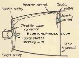
Figure 37. Steering and remote-control.
|
|
| The engine is used to steer the boat as well as to propel
it and this is achieved by swiveling the engine on a pivot by a tiller.
The Anzani engine can be completely turned round so that it will in fact
act as a reversing action to the drive. The Seagull will not do this.
It is unlikely that the skipper will want to stand by
the tiller the whole time and a remote-control steering wheel can be quite
easily rigged up on the outside of the bulk-head panel on the port side.
The various accessories for this remote control can be rigged up by the
inventive amateur but on the other hand parts may be bought quite inexpensively.
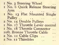
From the current list the following items would be needed: |
|
Steering and remote-control parts required.
|
|
|