Ballista - Build a Ballista
Ballista Design Plans
Roman Ballista Catapult
Roman stone throwing and arrow throwing torsion
ballista
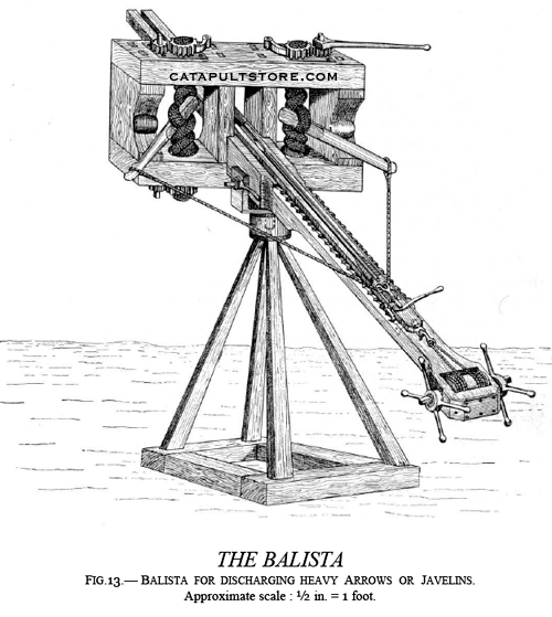
THE BALLISTA FIG.13. - BALLISTA FOR DISCHARGING HEAVY ARROWS OR
JAVELINS. Approximate scale : ½in. = 1 foot.
This engine is here shown ready for discharge with its
bow-string drawn to its full extent by the windlass. The heavy iron-tipped
arrow rests in the shallow wooden trough or groove which travels along
the stock.
The trough has a strip of wood, in the form of a keel,
fixed beneath it. This keel travels to or fro in a dove-tailed slot cut
along the upper surface of the stock for the greater part of its length.
( F, fig. 14.)
The arrow is laid in the trough before the bow-string
is stretched. (A, B, fig. 14.)
The ballista is made ready for use by turning the windlass.
The windlass pulls back the sliding trough, and the arrow resting in it,
along the stock of the engine, till the bow-string is at its proper tension
for discharging the projectile. ( Fig.13.)
As the trough and the arrow are drawn back together, the
arrow can be safely laid in position before the engine is prepared for
action. The catch for holding the bow-string, and the trigger for releasing
it, are fixed to the solid after end of the wooden trough. ( Fig. 14. )
The two ratchets at the sides of the after end of the
trough travel over and engage, as they pass along, the metal cogs fixed
on either side of the stock. ( Fig.14.)1
By this arrangement the trough can be securely retained,
in transit, at any point between the one it started from and the one it
attains when drawn back to its full extent by the windlass. As the lock
and trigger of the ballista are fixed to the after end of the sliding trough
( fig. 14. ), it will be realized that the arrow could be discharged at
any moment required in warfare, whether the bow-string was fully or only
partially stretched.
In this respect the ballista differed from the crossbow,
which it somewhat resembled, as in a crossbow the bow-string cannot be
set free by the trigger at an intermediate point, but only when it is drawn
to the lock of the weapon. It will be seen that the ballista derives its
power from two arms ; each with its separate skein of cord and pair of
winches. These parts of the ballista are the same in their action and mechanism
as those of the catapult.
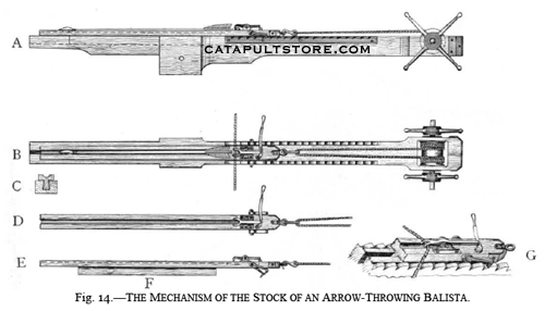
FIG. 14.- THE MECHANISM OF THE STOCK OF AN ARROW
THROWING BALLISTA.
A. Side view of the stock, with the arrow in the sliding
trough before the bow-string is stretched.
B. Surface view of the stock, with the arrow in the sliding
trough before the bow-string is stretched.
C. Section of the fore-end of the stock, and of the trough
which slides in and along it.
1 When
the bow-string has been released and the arrow discharged, the ratchets
are lifted clear of the cogs on the stock of the engine. This allows the
trough to be slid forward to its first position as shown in A, B, Fig.
14. It is then ready to be drawn back again for the next shot.
D. Surface view of the trough, with the trigger and catch
for the bowstring.
E. Side view, showing the keel (F) which slides along
the slot cut in the surface of the stock as the trough is drawn back by
the windlass.
G. Enlarged view of the solid end of the trough. This
sketch shows the catch for the bow-string, the trigger which sets it free,
the ratchets which engage the cogs on the sides of the stock, and the slot
cut in the stock for the dove-tailed keel of the trough to travel in.
Ballistas were constructed of different sizes for the
various purposes of siege and field warfare. The smallest of these engines
was not much larger than a heavy crossbow, though it more than equalled
the latter in power and range.
The small ballistas were chiefly used for shooting through
loopholes and from battlemented walls at an enemy assaulting with scaling
ladders and movable towers.
The largest had arms of 3 ft. to 4 ft. in length, and
skeins of twisted sinew of 6 in. to 8 in. in diameter.
Judging from models I have made and carefully experimented
with, it is certain that the more powerful ballistas of the ancients could
cast arrows, or rather feathered javelins, of from 5 to 6 lbs. weight,
to a range of from 450 to 500 yards.
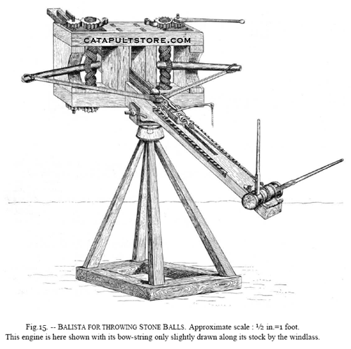
Fig.15. - BALlISTA FOR THROWING STONE BALLS. Approximate
scale : ½in.=1 foot. This engine is here shown with its bow-string only
slightly drawn along its stock by the windlass.
It will be seen that this engine is almost identical
in construction with the one last described. (Fig.13.)
The difference is that it propelled a stone ball instead
of a large arrow. The ball was driven along a square wooden trough, one-third
of the diameter of the ball being enclosed by the sides of the trough so
as to keep the missile in true direction after the bow-string was released.
The bow-string was in the form of a broad band, with an
enlargement at its center against which the ball rested.
The description given of the mechanism and management
of the engine for throwing arrows can be applied to the construction and
manipulation of this form of ballista, which was also made of large and
small dimensions.
Small engines with arms about 2 ft. in length and skeins
of cord about 4 in. in diameter, such as those I have built for experiment,
will send a stone ball, 1 lbs. in weight, from 300 to 350 yards. There
is little doubt that the large stone throwing ballista of the Greeks and
Romans was able to project a circular stone, of 6 to 8 lbs. weight, to
a distance of from 450 to 500 yards.1
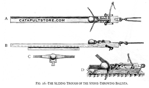
FIG. 16. - THE SLIDING TROUGH OF THE STONE THROWING
BALLISTA.
A. Surface view, with the stone in position.
B. Side view, with stone in position.
C. Front view of the stone as it rests in the trough against
the enlarged center of the bow-string.
D. Enlarged view of the solid end of the sliding trough.
This sketch shows the ball in position against the bow-string ; the catch
bolding the loop of the bowstring, and the pivoted trigger which, when
pulled, releases the catch.
One of thepair of ratchets which engage the cogs on the
sides of the stock, as the trough is drawn back by the windlass to make
ready the engine, is also shown. The trough has a keel to it, and slides
to or fro along the stock in the same manner as in the arrow throwing ballista.
(Fig.13.)
Compare with figs. 13 and 14, for further explanation
of details.
1 The balls used by the ancients in their catapults
and ballistas were often formed of heavy pebbles enclosed in baked clay,
the reason being that balls made in this way shattered on falling and hence
could not be shot back by the engines of the enemy. The ballistas for throwing
arrows, and those employed for casting stones, were fitted with axles and
wheels when constructed for use in field warfare.
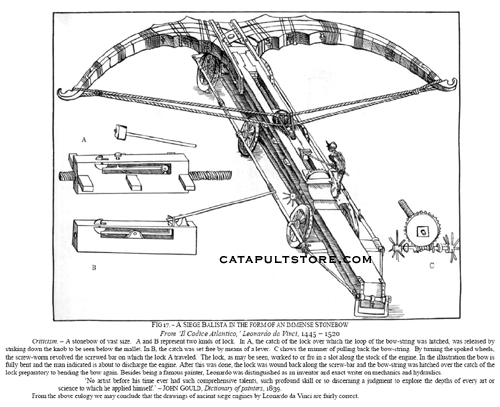
FIG 17. - A SIEGE BALLISTA IN THE FORM OF AN IMMENSE
STONEBOW From Codice Atlantico,Leonardo
da Vinci 1445 - 1520
Criticism. A stonebow of vast size. A and B represent
two kinds of lock. In A, the catch of the lock over which the loop of the
bow-string was hitched, was released by striking down the knob to be seen
below the mallet. In B, the catch was set free by means of a lever. C shows
the manner of pulling back the bow-string. By turning the spoked wheels,
the screw worm revolved the screwed bar on which the lock A traveled. The
lock, as may be seen, worked to or fro in a slot along the stock of the
engine. In the illustration the bow is fully bent and the man indicated
is about to discharge the engine. After this was done, the lock was wound
back along the scrubber and the bow-string was hitched over the catch of
the lock preparatory to bending the bow again. Besides being a famous painter,
Leonardo
was distinguished as an inventor and exact writer on mechanics and hydraulics.
No artist before his time ever had such comprehensive
talents, such profound skill or so discerning a judgment to explore the
depths of every art or science to which he applied himself. JOHN GOULD,
Dictionary of painters, 1839.